One of my favorite quotes on learning is from the television show Frasier. Kelsey Grammer, as the title character, best summed it up: “It may be an unwise man who doesn’t learn from his own mistakes, but it’s an absolute idiot that doesn’t learn from other people’s.”
How can we apply this valuable lesson to monitoring UV and establishing/maintaining a process window? Consider the real-world experiences below:
Trust but verify…
A manufacturer with multiple products utilizes UV LEDs on some assembly lines and broadband (arc) sources on others.
On products manufactured with the UV LEDs, the LED is extremely close to the product, and the process is optimized for a high-intensity, narrow-bandwidth (monochromatic) UV source. On products manufactured with a broadband (arc) lamp, the source is set up for far-field distant curing with low intensity levels. The UV sources on all assembly lines are well shielded, and the light source is not visible.
One production team was extremely frustrated with the readings from their radiometer. What they failed to consider was that an instrument optimized to measure 395 nm LED sources up to 40 W/cm2 of power was being used to measure their mercury-based source with an output of less than 50 mW/cm2.
When the production team switched to an instrument with the right response and proper dynamic range for the source, they quickly got back on track.
Lesson #1: Verify the type of source being used and match the instrument to it.
Clearly communicate your needs …
An industrial parts manufacturer partnered with a coating and LED supplier to develop a new product. Lab work established the key process parameters for the application, and a large number of LED sources were ordered based on laboratory trials. When the LED sources arrived, the cure results could not be replicated.
Further investigation and radiometer testing revealed that a 395 nm LED source was mistakenly ordered instead of the 365 nm LED that was specified. Once the correct wavelength LEDs were in place, production moved along smoothly.
Lesson #2: The purchasing team may be tasked with buying products that require special knowledge. Be clear: Specify part numbers, manufacturers, etc. Ask to review the purchase order or supplier’s sales order acknowledgment before delivery.
Don’t handcuff the transition team…
A medical product supplier assembled a team to transition from its current broadband UV source to an LED source. The formulation was being cured with a broadband source (H+ bulb), which is rich in UVC output, and the current process window called for an extremely tight UVC specification.
The transition team was told that, due to the regulatory process, no modifications could be made to the current formulation. Is it realistic to expect that a 365 nm LED will have the same ability to cure the product, given the requirement for UV energy in the shorter UVC wavelengths? To be certain, the transition team is testing a 365 nm LED.
Lesson #3: Have realistic expectations when transitioning to an LED source.
Look in the mirror …
A company working to develop a new UV LED process measured its LED laboratory system in August 2017. The project was put on hold, and when work resumed in January 2018, the team noticed a sharp decrease in radiometer readings. Following a conference call to discuss process variables and instrument care, the customer took additional readings and was convinced that the instrument had changed. When evaluated, it was found the instrument was reading correctly and was returned to the customer.
A new set of readings was obtained in February 2018, when the instrument was returned (Figure 1).

The first instinct of many companies when things are not curing is to “question” (blame) the formulator. However, in this case, the company was doing its own formulation. UV source suppliers are usually the next to be questioned. The company dismissed the idea that the UV source was a possible culprit in the drastic change because of the inherent stability of LEDs.
After further testing confirmed the radiometer’s performance, the company refocused its attention on the LED source. Careful inspection revealed that the optical glass on the LED array had been coated with a thin film of ink. After cleaning the ink from the face of the LED window, the instrument readings jumped back to the August 2017 levels.
Lesson #4: When things change, work through the process variables to understand what happened.
Trust but verify … Part 2
A customer with side-by-side LED units mounted across a curing conveyor obtained the readings in Figure 2 and wanted to understand the differences.

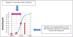
After some digging, it was discovered that the readings were taken with a radiometer not optimized for source type. The LED sources were 365 nm, and the instrument was optimized for a 395 nm source. One UV LED array had a center wave length (CWL) closer to 360 nm and the other was closer to 370 nm. When a radiometer with a proper response was used, the two different LED systems compared very closely.
Lesson #5: LED sources with similar specifications can vary slightly in their spectral output. These spectral differences were only noticed when an instrument with a response not matched to the source was used.

The Takeaways: Select the right instrument
Match your instrument to the source. Use an instrument with the correct:
- Dynamic range to the irradiance of the light source to be used
- Responsivity to the proper wavelengths used in your process
Instrument Dynamic Range
Radiometers designed for mercury sources have responses (and dynamic ranges) matched to the broadband output and the irradiance levels of a mercury-based source. You will get a “number” if you use a broadband radiometer to measure an LED, but the number most likely will not report the true value of the source. Work with the manufacturer to determine whether a particular instrument response and bandwidth range is matched to the type of source being measured.
UV LEDs are commonly sold with a +/- 5 nm CWL variation. A 395 nm LED can be expected to have its CWL output from 390 to 400 nm, and a 365 nm LED can be expected to have its CWL between 360 and 370 nm. An instrument with the correct responsivity and dynamic range will take the normal CWL variations into account when multiple sources are measured.
This column’s parting thought
Q: Does light have mass?
A: Of course not. It’s not even Catholic!


