

Bands were discussed in the last column and Ranges are discussed in this one. Together, these topics account for a large portion of EIT’s customer “education” efforts. Consistent UV measurements start with a radiometer with the correct band and range for your application.
Are we talking the same language in the context of UV curing?
Dynamic Exposure: continuously moving or changing. Your product/radiometer is exposed to varying irradiance levels when it passes under a UV source(s) or when a source(s) is passed over the product or the radiometer. At some point, the product or radiometer will “see” the “peak” UV intensity.
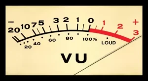 Dynamic Range: This is the span between the minimum and maximum irradiance to which a radiometer will accurately respond. It can be expressed as a ratio or in measured units (Watts/cm2). Making measurements above or below the levels for which the measurement device is designed provides misleading or useless information. If you have experienced a “pinned meter” when making measurements, you are familiar with the problem.
Suggested Operating Range: Some manufacturers will state the instrument range as the lowest and highest levels at which the instrument will operate to specifications (UVA, 100 mW/cm2– 10 W/cm2).
Start Threshold: This is the point at which the instrument will turn on and start counting UV. This is a function of instrument design and also is impacted by calibration factors. Measurements made near the start threshold are prone to significant variations.
How do you determine the best instrument range needed?
Weighing an infant on a truck scale or using a weather thermometer to measure the internal temperature on your holiday turkey can produce poor and dangerous results. Radiometers, like other instruments, need to be sized and matched to intensity of the UV source. Instrument manufacturers work hard to balance the amount and type (UV, Visible, IR) of energy impinging on their optics.
High amounts of energy allow for a faster instrument response and, when used with the appropriate electronics, allow instruments to be used at fast production speeds. Higher amounts of energy can saturate or “peg” detectors. Optical components, if exposed to high amounts of UV energy over an extended time, can degrade (solarize) with the instrument performance impacted.
To determine the correct instrument range (and also band), we ask questions, including:
Type of UV source?
- Broadband (arc, microwave, flood, spot, pulsed)
- LED (array, flood, spot)
Has the source supplier specified the expected UV output in terms of W/cm2 or mW/cm2?
- Clarify the values and what instrument was used?
- Is the output a wide band (UVA + UVB +UVC) or narrow band (UVA) value?
- If an LED, was the value right at the quartz window at 100% applied power?
If the source output is not available, we ask about the application.
- Does the customer have target irradiance values from the coating supplier?
- Clarify the values and what UV bands and instrument were used.
- If the customer only has energy density (mJ/cm2) targets, how long is the expected exposure when the speed changes? A process running with a single UV source at 40 fpm will give the same energy density as a process running at 80 fpm as long as the conditions and set-up of the two lamps are the same as those of the first lamp.
The effective energy density (“dose rate”) can have a dramatic effect in manufacturing processes on product performance. - How far away from the source is the cure/measurement location?
If two vehicles each consume five gallons of fuel, that information does not tell us about their travel range (fuel efficiency), horsepower, performance or cargo-carrying capacity. What if one vehicle is a motorcycle and the other a large truck?
The applied (input, consumed) electrical power of a UV system can be a source of confusion. The applied power for a light source can be expressed in multiple ways and, like the two vehicles, equal applied (consumed) power numbers do not mean equal output. We can sometimes work backward to get the correct instrument range.
A 300-Watt source consumes 300 Watts of electrical power. This is the total applied electrical power – not the UV output in mW/cm2 or W/cm2. When the applied power is described, we need to know the size of the array or source and the expected measurement distance.
The applied electrical power on sources with bulbs is described as the power consumed per bulb length. The amount of UV reaching the cure surface will vary based on how the UV source is set up, and the bulb type. A 600 Watts per Inch (240 Watts per Centimeter) mercury microwave source can deliver 6+ Watts /cm2 (UVA) when run in focus. This same source, used to cure medical products in a large chamber, will deliver less than 0.100 W/cm2 of UVA.
In a recent exchange, a customer asked for a way to measure a 300-Watt source. We initially assumed this meant a single 300-Watt UV source. Digging a little deeper, we discovered the source was 12 germicidal lamps rated at 75 Watts each, with 25 Watts in the UVC area. The 300-Watt rating came from the UVC band (12 lamps X 25 Watts each). The target energy density (50 to 600 J/m²) and irradiance (0.5 to 50 W/m²) values were based on the measurement distances between 1 and 5 meters. Both values were expressed in m2, not cm2. After a clarification and a little bit of math, we determined this application was not a fit for our products.
Curing applications ordinarily consider square centimeters (cm2) for the area (mW/cm2, W/cm2, J/cm2, mJ/cm2), however this is not the case for all applications. Double-checking is a good practice.
Instrument Operating Ranges
The level at which a radiometer is designed to turn on and begin measuring UV values is the Start Threshold. This threshold is a function of the instrument’s electronic design and optics. The actual start threshold can vary slightly from instrument to instrument, due to slight variations in optical stack and electronic components, as well as calibration factors. Eliminating any variation in these components would greatly increase the price of the instrument.
The UVA band in EIT’s 10-Watt Power Puck II has a recommended operating range 100 mW/cm² to 10 W/cm². The start threshold for this band in this instrument is 4 to 12 mW/cm2. When the instrument is used within the suggested operating range, the minor differences in the optics, electronics and start threshold are virtually eliminated.
Use your radiometer within the manufacturer’s suggested operating range, and use it with common sense. Question readings that do not make sense, and make sure you have the right instrument range.
When you use an instrument scaled for high-power sources on a low-power source:
- It measures below the suggested operating range of the instrument.
- Some runs may show up as zero, or the readings will vary run to run or instrument to instrument because of differences in the start threshold.
- You may see large variations in the Joules – especially on longer duration runs or exposures.
When you measure a high-power source with an instrument that is optimized for low-power sources:
- Be careful not to over-range or “peg” the irradiance values on the instrument. This can mislead you into thinking that your source is very stable.
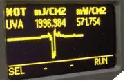
- Check with the manufacturer to see if the instrument warns of an over-range situation. On EIT’s Puck, an over-range is indicated by an *OR in the upper left corner of the display.
- Some instruments do not have the dynamic range to support high-power LEDs.
- Check your instrument to see if the display units need to be adjusted from mW-mJ/cm2 to W-J/cm2
- If the EIT LEDCure display is set to read mW-mJ, the highest value the instrument can display in this mode is 9999.99 mW/cm2. Adjust the display to W-J units to display values over 10 W/cm2
- If you have high-power source and are using an instrument optimized for lower-power sources, you also run the risk of prematurely damaging/solarizing the instrument optics with repeated exposures.
- Dynamic range is the span between the minimum and maximum irradiance to which a radiometer will accurately respond. The area where the instrument will accurately respond is the suggested operating range. Be careful of instruments with large dynamic ranges that may dip down into values that are closer to the start threshold instead of a region that will give you the best repeatable performance.
UV sources (including LEDs) can generate a good deal of heat. Understand the temperature limits on the radiometer and follow them to avoid damaging the instrument. Avoid IR and convection ovens, and let the instrument cool down between readings. The *OT display indicator, and/or audible warning indicate that the unit has reached an over-temperature situation.
Summary
 Two important themes emerge when it comes to “honing” in on the correct radiometer range:
Match the radiometer to the irradiance values of the curing process to assure accurate, repeatable measurements as well as the best performance and longevity of the device.
Multiple light sources with vastly different intensities may require instruments with different ranges, since a one-size-fits-all solution can yield unreliable results.
Parting Thoughts
I used to work at a company that made tiny measuring devices. It was a small-scale operation.
“They’ve done studies, you know. Sixty percent of the time, it works every time.” – Brian Fantana from the movie “Anchorman”
 Jim Raymont
Director of Sales
EIT LLC
jraymont@eit.com


