


Colorblindness has long been touted as an advantage of electron beam and a key differentiator between EB and UV technologies. And it’s true, the penetration of UV light is dependent on the optical clarity of the material it’s interacting with, while EB penetration is governed by material density (and chemical composition) – i.e., zip, zero, nada to do with color, opacity or any other visual metric. 1,2
Being colorblind, so to speak, affords EB several advantages in comparison to UV. There’s typically no need to make adjustments to production settings – more lamps, slower speeds, etc. – to accommodate different-color inks. UV inks might require more photoinitiator or other changes to the PI package to achieve proper cure of different colors. These types of formulation changes are not necessary with EB. EB often can cure more highly pigmented and thicker ink layers, leading to richer colors, brighter whites and blacker blacks, and reducing the need for pigmented substrates. Reflective and/or metallic inks are not problematic for EB. EB even can penetrate through a completely opaque laminate to polymerize a laminating adhesive.
Being colorblind does not make an EB-curable formulation wholly impervious to the addition of pigments, fillers or other additives, however. UV and EB formulations generally use similar monomers and oligomers to make up the bulk of an ink, adhesive or coating, so – independent of the cure mechanism – there are physical limitations to how much pigment can be properly dispersed or additive dissolved in these chemistries. Similarly, the majority of industrial applications for both UV and EB utilize free-radical chemistry; therefore, any pigment or additive that would inhibit a free-radical reaction would be detrimental to both technologies. 1
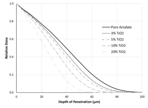
For EB, one of the most influential ways pigments, fillers and other additives affect the system is their contribution to the average density. If these components increase the density of the formulation, they decrease the penetration of the electron beam. Figure 1 demonstrates this principle using Monte Carlo simulations. TiO2, a common white pigment, has a density of 4.26 g/cm3. The acrylate that the pigment is being incorporated into only has a density of 1.06 g/cm3. Therefore, as the fraction of TiO2 in the formulation increases, the average density of the formulation also increases. When the formulation is 20% TiO2, 80% acrylate, the density has increased to 1.7 g/cm3. Penetrating a 20-µm thick, pure acrylate coating at 100 kV, approximately 75% of the surface dose remains (Figure 1). In the same scenario with the 20% TiO2 formulation, the dose level at 20 µm is reduced to ~60% of the surface dose.
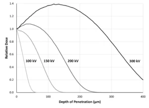
In Figure 1, the data was modeled using an accelerating voltage of 100 kV, which is a typical setting for the curing of inks and coatings. However, this is an adjustable setting on low-energy (≤ 300 kV) electron beams. If 100 kV isn’t sufficient penetration for thicker inks/coatings or laminates, the accelerating voltage can be increased until the maximum machine capacity is reached. Figure 2 illustrates how increasing the voltage significantly can change the penetration of the beam through a material, specifically 20% TiO2 and 80% acrylate.
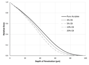
After evaluating just Figure 1, the reader might be tempted to believe that EB is dependent, at least somewhat, on color. Although the density increases with increasing amounts of TiO2, so too does the opacity of the system. In fact, often pigments have a higher density than the pre-polymer system to which they’re added, somewhat complicating this explanation with a bit of correlation. Thus, two additional pieces of evidence have been included! First, the simulations in Figure 1 were repeated with carbon black, which has a density of 1.9 g/cm3 (Figure 2). In comparing Figures 1 and 3, one will notice that, because carbon black does not increase the formulation density as quickly as TiO2, adding carbon black does not have the same impact on depth of penetration (even though it certainly impacts optical clarity). With a formulation of 20% carbon black, 80% acrylate (average density of 1.23 g/cm3), a dose level of approximately 73% of the surface dose is delivered at 20 µm, only slightly different that that of the pure acrylate.
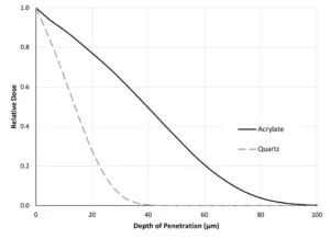
Second, two clear materials – the pure acrylate and quartz – are compared in Figure 4. With quartz having a density of 2.65 g/cm3, the beam penetration is more limited in quartz than in the acrylate.
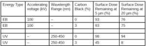
To summarize, UV and EB – photons and electrons – are governed by different physical principles, which results in UV being affected by optical density whereas EB is affected by material density. Including pigments or additives can affect the material density of the formulation as well as the optical density, so EB penetration into a material may be reduced; however, the impact of optical density on UV tends to be much more restrictive in these situations, making EB a good choice for heavily pigmented inks and coatings. Table 1 compares how EB and UV respond to the addition of 3 wt% carbon black. The slight increase in material density makes a slight decrease in EB penetration, but the increase in optical density drastically decreases UV penetration.
EB also has the added advantage of energy penetration control through accelerating voltage (Figure 2). 2,3 Should a heavy pigment loading decrease the beam’s penetration, a quick change to the voltage setting on the HMI can bring it right back. Whatever the application, the next time your UV process is challenged by color or opacity, consider what opportunities implementing colorblind EB could bring.
References
- Odian, G., Principles of Polymerization, John Wiley and Sons (2004).
- Spinks, R.J., Pikaev, A.K, Applied Radiation Chemistry: Radiation Processing, John Wiley and Sons (1994).
- Thiher, N.L.K., Schissel, S.M., Jessop, J.L.P., Quantifying UV/EB dual cure for successful mitigation of oxygen inhibition and light attenuation, Progress in Organic Coatings, 138 (2020).
 Sage Schissel, Ph.D.
Applications Specialist
PCT Ebeam and Integration LLC
sage.schissel@pctebi.com


