


By Bob Malone and John Phillips, Miltec UV
Is your UV curing system not performing as it should? Are you constantly replacing overheated lamps? Maintaining a healthy UV curing system is crucial to obtain successful results in curing and save money by reducing unexpected downtime caused by poorly maintained UV equipment. There are five main ingredients that make up a healthy UV system. These include proper lamp cooling with adequate airflow, power supply maintenance, proper light shielding, maintaining the reflector condition and lamp maintenance. Paying close attention to each one of these may solve existing, ongoing problems with your UV curing process, or it may prevent curing problems that you might otherwise experience with your equipment. The five topics that will be discussed apply to both arc lamp UV systems and microwave-powered (electrodeless) UV lamp systems.
Cooling and airflow
It is critical for virtually all UV curing lamp systems to maintain proper air-cooling delivered to the lamp to ensure a heathy UV curing system. UV lamps operate at very high temperatures (at around 800°C or 1,500°F bulb surface temperature) in order to maintain a consistent, fully developed mercury plasma state inside the UV bulb. More advanced UV lamp systems require a cooling system that not only maintains the lamp stability in that range but also protects the integrity of the metal structure in which the lamp is operating. The most common method to cool a UV lamp is with air flowing through its housing and across the UV bulb and reflector. However, to ensure consistent UV output and long life of your UV bulbs, several things should be considered when designing a proper UV lamp air-cooling system.
UV lamps do have a “cooling window” when it comes to proper air cooling. They can be over-cooled or under-cooled. To make it a bit more complicated, the required amount of air cooling that is to be delivered past the UV bulb will depend on the power level at which you operate the UV lamp. Most modern UV lamp systems are powered by variable power ballasts, which can deliver a power range from 20% to 100%. Such a wide power adjustment range will allow the lamp to be changed from about 130 W/inch up to about 650 W/inch. For some UV systems, the power setting is adjusted by the front panel controls, but for more sophisticated UV systems, the lamp power is automatically adjusted as a function of line speed via a 0 to 10 VDC or 4 to 20 milliamp signal provided by the customer. As the lamp ramps up in power, it requires more cooling air delivered past the UV bulb to prevent overheating. Conversely, as the lamp power is reduced, the cooling air must be reduced to ensure the lamp is not overcooled. Consequently, to avoid lamp cooling problems, it is essential that the cooling system adjust automatically to match the lamp power and heat load to maintain stability of the lamp and ensure that it operates within its proper temperature range. Operating lamps in an overheated condition will result in shortened lamp life and possible lamp swelling or warping, which adversely affects the UV output. Lamps that operate in an overcooled condition will suffer from shortened lamp life and low UV output as well. When a lamp is overcooling, it cannot develop the correct voltage, and the current (amps) remains high, putting adverse wear on the electrodes over time. In most cases when the lamp is overcooled, the mercury plasma will begin to become unstable and the lamp will inadvertently extinguish. Only when a lamp is operating within the correct cooling parameters consistently will maximum lifespan of the UV bulb be realized and consistent output from the UV bulb be achieved.
Reflector condition
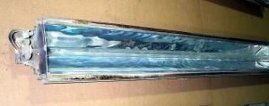
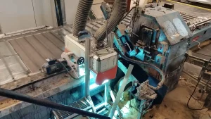
Another critical part of any UV system that must be maintained to ensure a healthy curing system is the condition and performance of the reflector, which typically is in the shape of a semi-elliptical or parabolic geometry that wraps around the upper half of the bulb and runs the full length of the UV bulb. Figure 1 shows an overheated reflector. The lamp reflectors are an important part of the UV lamp system because they are typically responsible for reflecting about 65% of the UV energy emitted from the bulb to the customer’s product, shown in the reflector/light-ray diagram in Figure 2. When the reflectors are not cooled properly, they can warp and wrinkle as a result of thermal expansion. Reflectors that lose their curved shape will cause the light ray pattern that reflects toward the customer’s product to become scattered or diffused, which will negatively impact its ability to cure.
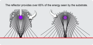
Figure 2 illustrates two conventional light ray patterns that are used in most UV curing systems. It is essential that the curved shape of the reflector does not change during lamp operation in order to maintain these UV light ray patterns. The curved shape of the reflectors is typically designed to concentrate (or focus) the light rays to a very small area, creating extremely high UV peak irradiance at the customer’s product, which is one of the keys to UV curing. In addition to maintaining the desired reflector curve, routine maintenance to the reflector also is extremely important. When the reflectors become dirty, contaminated or dulled over a period of usage, the percentage of reflectivity is reduced significantly, in turn reducing the UV energy and intensity delivered to the product. Poor reflector conditions will result in uncured product. The reflector is considered a consumable part for all UV systems, and it is a component that requires attention and maintenance (or periodic cleaning) to help ensure consistent UV output from the lamp system.
Some UV systems use replaceable reflector liners, which are normally made of a thin, polished aluminum material with a protective coating (which looks much like a conventional mirror finish) and typically pre-curved and cut to fit into a reflector holder inside the lamp housing. Other UV lamps use “cold mirror” reflectors, which also are thin, pre-curved and cut aluminum or glass reflectors that are held in a holder of some type inside the lamp housing. Cold mirror reflectors have special coatings applied to the reflective side of the substrate. They are designed to efficiently reflect UV light but absorb the IR energy (heat) emitted by a UV bulb. Cold mirror reflectors will reduce the heat load on the customer’s product as it travels under the UV lamps. Less sophisticated UV systems use a polished aluminum extrusion as the reflector, which is curved around the UV bulb and acts as a reflector and a lamp shutter. Regardless of the reflector type, it is important that the reflector condition is maintained with a clean, shiny appearance. If the reflector begins to look dull or dirty, it needs to be cleaned or replaced. Reflectors can be cleaned using a lint-free cloth and isopropyl alcohol or a surface cleaner that does not leave a film. Cleaners that contain ammonia are not recommended. If, after cleaning, the reflector still appears to be dull or dirty, it should be replaced. In almost all cases, a dirty or dulled reflector will have more impact on UV output reduction than an old, poor performing UV bulb. Measuring the UV output also will help diagnose a poor performing reflector. The best device that is available to measure UV output is a “puck” style radiometer that measures UV energy in all four UV ranges: UVA, UVB, UVC and UVV. The puck style radiometer is placed on the conveyor belt and run under the UV lamp at some pre-defined constant speed. It will measure the total UV energy delivered by the lamp. When the UV energy reduces to a point where there is danger of not achieving proper cure, then it is most likely time to clean and/or replace the lamp reflector.
Lamp maintenance
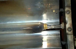
Routine lamp maintenance also is key to maintaining a healthy UV curing system. Most UV lamps operate in industrial environments, which are typically less than ideal conditions. It is important to try to keep the lamp as clean as possible to help ensure consistent UV output and prolong its useful life. Neglected lamps will suffer from low UV output, age quickly and fail prematurely. The simplest way to keep UV bulbs clean is by cleaning them with a designated UV glass bulb cleaner and a lint-free cloth. The frequency of cleaning the UV bulbs will vary, depending on the environment in which they are operating. Dirty and contaminated UV bulbs that operate for prolonged periods of time are more prone to overheating, and then swelling or warping (Figure 3). If a UV bulb swells or warps, it will negatively impact the UV peak irradiance output of the lamp and the system’s curing performance. Once a UV bulb appears swollen or warped, it should be replaced. If air filters are used to help keep the lamp-cooling air clean (which is common for microwave-powered UV lamp systems), then it is important to change these filters regularly to help ensure the lamp-cooling air delivered into the housing and past the UV bulb (and reflector) is clean. Maintaining clean air filters also helps ensure that the volume of air delivered to the lamp is maintained within the required specification. Operating a UV lamp system with dirty and clogged air filters will almost always result in overheated UV bulbs and a significant reduction in bulb life.
Power supply maintenance
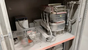
Let’s move onto the next reason why maintaining a healthy UV curing system is important: power supply maintenance. The heart of any UV system is the expensive power supply that drives the UV lamp. Whether a conventional iron core ballast or a solid-state power unit is used, the proper volume of filtered cooling airflow delivered to the ballast is critical to the health and life expectancy of any ballast and other electrical components inside the ballast enclosure. Power supplies operating in a dirty or overheated environment will deteriorate or fail prematurely, resulting in low UV output or lost production. Maintaining a clean air filter and the proper amount of air flow to the ballast will ensure the ballasts are properly cooled and kept clean. Air filters should be replaced as often as needed, depending on the environment. In the event the ballast and other internal power supply components (such as capacitors) become coated with dirt or dust (as shown in Figure 4), it is highly recommended to do two things:
Check the air filter, and replace it if needed.
Blow out the ballast and all other internal components with clean, dry compressed air, and then vacuum out the settled dust.
Light shielding
The last ingredient to maintaining a healthy UV curing system involves light shielding. The primary purpose of light shielding is to protect personnel from any direct UV light exposure (Figure 5). Good shielding in and around the UV lamp housing will protect the lamp module components and the production machine to which it mounts. A properly designed light shield will prevent any machine hardware near the UV lamp from reaching unsafe temperatures or deteriorating from direct UV exposure. The secondary function of the light shield is to support the UV lamp housing in such a manner that it will efficiently cure the product. If the light shielding is removed from the machine for equipment maintenance, it is critical that it be reinstalled in the same position and location to ensure the lamp is positioned in the correct location and orientation. The third function of the light shield is its contribution toward good air cooling. Some light shields may have air intake vents or louvers to allow air to enter the inside the light shield for lamp cooling, substrate cooling and/or light shield cooling. If the air intake vents become clogged with dust or dirt, it can cause an increase in temperature of the UV lamp, light shield and the substrate. The result can be poor lamp performance, short bulb life or overheating the customer’s substrate. Periodically cleaning out the air intake vents (or louvers) on the light shield with brushes and a vacuum, or by blowing them out with dry compressed air should be part of the routine preventive maintenance schedule.
Conclusion
Five keys to maintaining a healthy UV curing system include: proper lamp air cooling, power supply maintenance, proper light shielding, maintaining good reflector condition and performing routine lamp maintenance. Keeping the system in healthy condition enhances its performance, saves down time, maintains personnel safety and results in proper cure.
Miltec UV’s service department plays an important role in helping our customers maintain their UV equipment properly, as well as helping our customers troubleshoot technical problems with virtually all UV equipment. The Miltec UV team is committed to helping you understand UV curing and address UV process related questions and issues. We possess the expertise to answer questions and help solve problems. Furthermore, we offer customized UV system training for our customers, including basic to advanced UV curing equipment maintenance, UV measurement and microwave and arc lamp technology. If in need of a new UV system, we can assist with that as well. Miltec manufactures the highest output and most user-friendly UV system that is available in today’s UV curing industry. Miltec can offer arc lamp UV systems, microwave powered UV systems and LED UV systems. For more information, visit www.miltec.com.


