


By Mehrgan Khavari, 3D Systems Corporation
In 2017, 3D Systems’ digital light processing (DLP)-based technology – known as Figure 4® – was introduced. The technology is a derivative of stereolithography (SLA) where a 3D model is sliced into two-dimensional images and the images are sequentially flashed on the bottom of a resin tray equipped with a light-permeable, oxygen-permeable membrane. The images are exposed using a digital light processing (DLP) chip. Each image is exposed with UV LED at 405 nm wavelength, activating the photoinitiator in the resin, which kicks off a free radical polymerization, converting the liquid to a solid, while the z-axis advances out of the pool of liquid, thus building, layer by layer, a solid material from the bottom up.
Since the introduction of the DLP-based system, corporate engineers and scientists have been rapidly developing a portfolio of materials that expand the applications of additive manufacturing. One important property is the heat deflection temperature (HDT), which suggests one limit of the use of a given material. This paper describes the efforts to achieve thermal and mechanical properties of typical thermoplastics – like polyetherimide (PEI) and polyether ether ketone (PEEK) – with a thermosetting photopolymer, referred to in this article as HIGH TEMP.
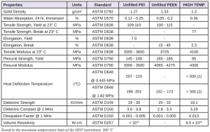
The HIGH TEMP material, based on a mixture of (meth)acrylate monomers, has achieved many of the properties shown in Table 1. Developing a high-temperature material had its own share of challenges, such as eliminating phase instability and achieving stable thermal integrity without the need for thermal curing (dual cure). This article discusses these unique challenges and solutions in more detail.
Background
To meet the requirement for heat-resistant applications, the material of choice must exhibit thermal characteristics at least comparable to existing materials on the market. Polyetherimide (PEI) and polyether ether ketone (PEEK) are well-known thermoplastic materials used in injection molding, as well as 3D printing technologies such as fused deposition modeling (FDM) and selective laser sintering (SLS). These materials are in demand for applications when part accuracy, mechanical and thermal properties are required at high temperatures.
The author’s company recognized a need for a high-temperature material for the proprietary printing technology that could compete with PEI and PEEK. In the early days of the project, cyanate esters were considered as a hybrid option, with acrylates to achieve high-temperature capability.
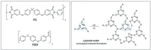
However, this endeavor was proven problematic. Figure 1 depicts the molecular structure of PEI, PEEK and cyanate ester.
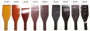
Cyanate ester, a thermoset material with a high glass-transition temperature (Tg) required thermal curing to achieve thermal stability at high temperatures. Also, cyanate esters did not participate in the free-radical photopolymerization with acrylates to form a network. Instead, the cyanate ester monomers phase separated into submicron size inclusions upon thermal post-curing, bloomed to the surface and solidified to form a textured surface. Figure 2 shows a hybrid mixture of acrylates and cyanate esters with increasing cyanate ester loading from left to right. As the cyanate ester loading increased, the surface of the parts changed from glossy to matte and – at loading greater than 50 wt% – clear signs of blooming and phase separation were evident.
Any exotherm that accompanied UV curing did not generate enough of the heat required to fully cure the cyanate ester components. Therefore, the unreacted cyanate ester phase behaved as a plasticizer, preventing the material from developing into a high Tg or heat distortion temperature (HDT) material. As a result, a heat treatment step was introduced during which the parts were taken to 250° C for one hour. However, heat treatment of a formulation with 50 wt% or more cyanate ester resulted in embrittlement of the material.
Choosing the Right Components
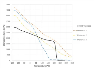
A search was begun to find a suitable UV-curing chemistry that could produce properties like those of PEI and PEEK. Figure 3 shows the storage modulus as measured by dynamic mechanical analysis of a PEI polymer, ULTEM™-10004, and several high Tg (meth)acrylate functional monomers across test temperatures ranging from -130° C to 330° C. Each monomer was mixed with 1 wt% photoinitiator and photocured by casting in a shape of a 3 mm by 6 mm by 35 mm bar. Used as a reference, ULTEM™-1000 showed a gradual decrease in storage modulus from -130° C and ~2900 MPa to about 200° C and 1800 MPa. Upon exceeding 200° C, it dropped quickly to zero, suggesting the softening and loss of mechanical integrity. Of the three (meth)acrylate-functional monomers, only one monomer showed storage modulus higher than ULTEM™ throughout the entire temperature range. The second monomer exhibited limited performance, because, in the temperature range between 60° C and 210° C, ULTEM™ had a higher storage modulus, yet at 220° C, the second monomer still exhibited ~1000 MPa in storage modulus. The storage modulus of the third monomer was higher than ULTEM™ only below 60° C, beyond which the modulus dropped precipitously.
Shelf-life and Phase Stability
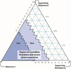
For high-temperature applications, phase stability is important. In the early formulation attempts, resins made with more than a critical amount of monomer resulted in shelf-life instability, with formation of solids in the bottle within two weeks at ambient temperature and in hours at temperatures less than 10° C. Monomer 1 can form a stable liquid phase at lower concentrations, as shown conceptually in Figure 4. However, experiments revealed that no place on the ternary diagram indicated a region where both high HDT and shelf-life stability co-existed.
In many cases, when a mixture contains a monomer that crystalizes to form precipitates, it is possible to add another monomer to the mixture to disrupt crystal formation. Screening
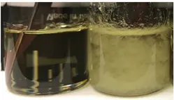
experiments showed that several monomers helped reduce and, in some cases, eliminate the crystalline formation. However, only one monomer produced high HDT values in the range greater than 200° C. Figure 5 shows two vials containing the final formulation. The one on the left was stabilized, whereas the one on the right was not, thereby phase separating.5
Circumvented Defects
The proper choice of monomers was important for the mechanical integrity of the material at high temperatures. Formulated with a given monomer, for example, a material may look fine after UV post-curing at room temperature. However, when exposed to high temperatures, it might develop internal defects, causing mechanical failure. These void-like defects may be the result of the unreacted monomers volatilizing. Figure 6a is a photograph of a formulation that formed internal voids when the material was heated to 230° C in a thermal oven. However, by reducing the monomer loading, a more stable material was created, as seen in Figure 6b.
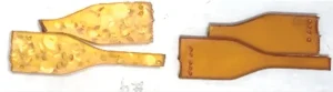
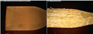
Defects also can arise when the cleaning process is too harsh or the solvent is too aggressive. After parts are printed and removed from the printer, they must undergo a wash process to remove unreacted resin. Cleaning recipes for all Figure 4® materials have been published6. During the development of HIGH TEMP researchers identified several cleaning processes that must be avoided. One example is sonication cleaning. Ultrasonic cleaning resulted in a decrease in tensile properties and, in some instances, caused formation of micro-cracks on the surface. Figure 7 shows pictures of cleaned parts. As seen in Figure 7a, a printed bar that was cleaned by ultrasonic cleaning in a soya-based cleaner showed surface micro-cracking. In another instance, Figure 7b, propylene carbonate was used as a wash solvent, and severe surface cracking occurred. These cracks were formed after UV post-curing. The company recommends mechanical agitation in isopropyl alcohol as the default cleaning process for HIGH TEMP. As seen in Figure 7c, no defects formed.
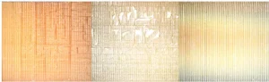
The benefit of UV post-curing: The light engine in the proprietary printer produces roughly 9 to 13 mW/cm2 at 405 nm. This light intensity, and the duration of the exposure, is only sufficient to fuse each newly printed layer to the previous layer. After the wash process, the material undergoes a more comprehensive UV cure, known as post-curing, and it is usually for longer than one hour. The post-curing cycle, during which the material is exposed to high-intensity UV, promotes bonding of the layers to each other and drives reaction conversion of unreacted monomers. Figure 8 shows the benefit of UV post-curing for HIGH TEMP. Figure 8a is a part that underwent UV post-curing for a minimum of 30 minutes. Figure 8b reveals significant cracking in the bulk and surface of the material that was not post-cured. The cracks are formed and only become visible when the parts are heated to 200° C.
Conclusion
Challenges of creating HIGH TEMP included proper formulation and process design. Experimentation revealed that using the right components in the right amounts was important to eliminate solution phase instabilities and achieve the desired properties. Other factors included UV post-curing and cleaning. By optimizing these processes, the author’s company was able to deliver a material comparable to those made with PEI and PEEK in fused deposition modeling (FDM) and selective laser sintering (SLS).
Mehrgan Khavari is a materials research and development specialist for 3D Systems Corporation in Wilsonville, Oregon. He can be reached at 503.482.1974, mehrgan.khavari@3dsystems.com or www.3dsystems.com.
References
- https://polymerdatabase.com/Commercial%20Polymers/PEI.html
- https://polymerdatabase.com/Commercial%20Polymers/PEEK.html
- https://www.3dsystems.com/sites/default/files/2020-07/3d-systems-figure-4-hi-temp-300-amb-datasheet-usen-2020-07-02-web.pdf
- https://www.sabic.com/en/products/specialties/ultem-resins/ultem-resin
- US2021095094A1, Optically Active Build Materials for 3D Printing, M. Khavari, K. Moussa, and S. Broce)
- http://infocenter.3dsystems.com/figure4modular/post-processing/cleaning-parts-printed-figure-4-resins/figure-4-cleaning-charts


