

By R.J. Viereckl, Michael Gould, Volker Petry, Rich Dodd, Xavier Marguerettaz and Sean Des Roches
Rahn USA
3D printing is a technique that has been employed for much longer than one would intuitively expect. Lamination-style creation is a well-known type of printing used in the making of 3D objects, for instance, in clay pot construction. Coils of wet clay1 can be stacked and pressed together to form a taller structure than would be possible otherwise. Modern 3D printing technology works in a similar fashion – i.e., building layer upon layer – and was first patented in 19842, considerably earlier than the current technological explosion. Recent progress might be attributed to the original patent’s expiration3, but it can also be attributed to the enormous improvement in computing power4. This has not only helped the additive manufacturing market but also the subtractive manufacturing market, with the invention of the computer numeric control (CNC) machine.
There are two main types of 3D printing: metal and plastic. Most metal printers use a powder bed and intense laser light to sinter parts together5. Due to the extreme power requirements of metal 3D printing, this technology is limited to specialized industries that strictly require metal parts, but the technology is improving every day. The plastics 3D printing industry is much easier to enter. Inexpensive materials, such as polylactic acid (PLA) and low-hazard machines combine to create a low barrier to entry. Plastics can either be melted and redeposited onto a growing object, or selectively polymerized to form a plastic thermoset polymer. These two techniques are referred to as fused deposition modeling (FDM) and vat polymerization, respectively. Formulating theory for vat 3D printing will be the focus of this paper, particularly for stereolithography (SLA)-type printing, with a few starting point formulations following the theory and implementation.
Vat polymerization is the umbrella term for SLA, digital light processing (DLP), and continuous liquid interface production (CLIP)-type 3D printing. These techniques are all employed for their high precision, small footprint and wide variety of available materials. SLA and DLP printers differ only in their UV exposure technique, but the underlying mechanisms are identical. In stereolithographic printing, otherwise known as SLA, a laser draws out a slice of a computer-assisted design (CAD) file, curing the prepolymer resin in the process. The layer is either then peeled off a nonstick base constructed of polydimethylsiloxane (PDMS) or fluroethylene propylene co-polymer (FEP), or the stage is lowered and more prepolymer resin is swept over the cured print6.
Direct light projection machines, or DLP printers, utilize the same mechanism; however, instead of a laser drawing out each slice, a projector exposes the entire CAD slice at once7. Thereafter, the process continues identically to SLA. In continuous liquid interface polymerization, or CLIP technology, the print proceeds in a continuous manner, as opposed to stepwise, as in in SLA or DLP. This necessitates an upside-down process, as the prepolymer resin needs to be continuously replenished as the curing object moves upward. Because of this, CLIP printers use a projector light source, similar to DLP printers, allowing them to continuously cure each slice of the object.
The mechanics of how each printer works are of utmost importance, as they limit the materials that can be used in each method according to mechanical properties of the printed part and the compatibility of components. This paper will specifically explore the mechanics of the Form 1+ SLA type 3D printer.
The Form 1+ is an inverted SLA machine, which means that the cured object being built is drawn upward from the prepolymer resin vat. The vat is constructed of acrylic plastic coated with a PDMS layer to act as a nonstick coating and cushion. To begin printing, the vat is filled with a prepolymer resin, an .stl file (file format also known as “standard triangle language” or “standard tessellation language” is imported into the machine, and a metal stage descends into the resin, compressing the resin into the PDMS. Next, the laser draws out the first slice of the object, and the first layer of the print is cured onto the stage. The vat slowly tilts sideways to peel the first layer off the PDMS. The metal stage rises again, the vat tilts back to level, and the stage lowers to stop one layer height above the PDMS. The laser draws the next slice, and the process repeats.
From these mechanical processes, three general formulation constraints are defined. First, all components of the formulation should be compatible with the PDMS and the acrylic plastic vat. The PDMS can and will absorb low molecular weight components, which, if cured while inside the PDMS matrix, will tear it. As an example, PDMS immersed in isobornyl acrylate (IBOA) for 48 hours swells to 187% of its starting weight. This causes severe warping, which leads to print failures and general printer damage. Products should be used only if they swell the PDMS by 10% or less over a 48-hour immersion period. Similarly, the acrylic plastic can be dissolved by certain components. The acrylic plastic, if immersed in dimethyl acrylamide (DMAA), will dissolve in 24 hours. This is a serious concern, not only for the preservation of the printer, but also for user safety. Since most print intervals only take a few hours, small quantities of these materials can be used. However, it is recommended to consider compatible alternatives. Not all printers use PDMS and acrylic plastic, so individual considerations change depending on the printer used.
The second formulation constraint involves the mechanical strengths of the formulation being printed. The main consideration is given to the overall reactivity of the formulation. Two components with similar ultimate mechanical properties, but differing reactivity, will have dissimilar green strengths if exposed to the same dose of curing radiation. This can be used to a formulator’s advantage, as an under-cured object will put less stress on the components of the printer, leading to a longer useful lifespan. However, the object must be cured enough to maintain cohesion during the peeling process. A small addendum to this constraint is that formulations with very low cohesive strength are difficult to print alone. These formulations typically contain components that have very low tensile moduli (E mod) and low glass-transition temperatures (Tg). Formulations of this nature usually require reinforcement or risk failure in the form of delamination.
The explanation for this constraint is found in the way printers detach objects from the vat. The PDMS acts as an oxygen source9 to inhibit direct, mechanical adhesion between the vat and stage. However, the printed/cured layer still adheres slightly. This results from the vacuum-suction effect known as Stefan Adhesion10 and is the reason the print is pulled down during the peel process. If the object is to survive and not delaminate from itself or the metal build platform, it needs to withstand these stresses with enough structural integrity to detach from the vat. Reinforcement can come either from higher Tg, oligomers or monomers, or in the form of inert fillers.
The third general formulation constraint relates to Stefan Adhesion as well: the viscosity of the formulation. High-viscosity formulations drastically increase the forces “pulling” on the print, while low-viscosity formulations decrease these forces. Stefan Adhesion also can be affected by the speed of the peel motor, i.e., a faster peel sees greater resistance. From this, it is advantageous to keep formulations near or below 1,000 mPa.
Making the jump from theory to practice can be difficult, but following these guidelines can help prints succeed more often than they fail. The first constraint is quite easy to address, as a preliminary screening of the component absorption is all that is needed to determine compatibility. The second and third guidelines are more difficult to balance from a formulation standpoint – and all must work together toward the final formulation goals. For example, a tough formulation should not use too much brittle monomer, no matter what diluting power it may provide. Or, a flexible formulation should not use too much of a stiff, brittle component, no matter how much reinforcement it will give.
Moving into more applicable theory, the mechanical properties of raw components can be used to significantly influence the final properties of a formulation.
Five integral properties of each component can determine how it will influence a 3D formulation. These properties are the glass transition temperature, volumetric shrinkage, tensile modulus, tensile strength and extensibility. All of these properties can be manipulated to make a formulation tough, hard or flexible. And different combinations of these properties can be extremely useful in preliminary formulation work.
For example, in flexible formulations, low Tg, low elastic modulus (E mod), high elongation products show the best results. In hard formulations, just the opposite is needed: A high Tg and high E mod components produce objects with very high hardness. These hard formulations can be brittle though, so a small amount of high elongation component can be added to prevent shattering and post-cure cracking. Additionally, hard components tend to have high curing shrinkage, which induces additional stress and leads to even more brittleness. Low shrinkage and flexible components can help minimize these stresses. To get from a hard formulation to a tough formulation, brittleness needs to be eliminated, rather than just mitigated. Benchmark tough plastics (e.g. acrylonitrile butadiene styrene or ABS) deform under load before breaking, while brittle materials do not. Thus, tough formulations should be built to emulate this.
Other components may not affect the final mechanical properties of a formulation, but instead will influence how successfully an object prints. These components – such as UV blockers, photoinitiator type and concentration, and surface curing additives – all can determine whether or not a formulation will print well.
The first – and most important – non-resin component is the UV blocker. Blockers are used to decrease the penetrating power of the light so that fine details and embossing can be printed, i.e., only one layer fully cures at a time, and light does not cure any layers beyond the site of exposure. It is important to note that only UV blockers are suitable for this application. Stabilizers (e.g. hindered amine light stabilizers, or HALS) do nothing to decrease the depth of light penetration. Most pigments will block UV light, and added pigment is the simplest way to add the required blocker for a formulation. Clear formulations also can be made by using fluorescent optical brighteners.
All formulations in this paper will use weight percent of 2,5-bis(5-tert-butyl-benzoxazol-2-yl)thiophene, CAS # 7128-64-5 (referenced here as OB) as the blocker. Less reactive formulations are generally more sensitive to blockers, allowing for predictable improvement in print accuracy. This might be why methacrylates work well in 3D printed formulations, given their lower reactivity and shrinkage compared to acrylates.
The second critical non-resin component is the photoinitiator. Long wavelength photoinitiators are typically used for smaller, consumer-grade printers, as the light required to initiate them is less hazardous and easier to implement.
Industrial grade SLA printers are not constrained in the same way and have a broader range of photoinitiators from which to choose. The two main photoinitiators used in the consumer world are phenyl-bis(2,4,6-trimethylbenzoyl)phosphine oxide (BAPO) and diphenyl(2,4,6-trimethylbenzoyl)phosphine oxide (TPO). Other photoinitiators can be used and also can help to decrease the surface tack of post-cured objects (such as 1-hydroxycyclohexyl phenyl ketone [CPK], 2-benzyl-2-dimethylamino-4’-morpholinobutyrophenone [BDMM], and thioxanthone [ITX]), however, only the two main initiators, BAPO and TPO, will be listed in the example formulations.
The concentration of photoinitiator is very important in 3D formulations. Too much, and prints may overcome the oxygen inhibition of the nonstick film and adhere to the vat. Too little, and the prints will not have enough green strength to maintain integrity during the print process. The optimum photoinitiator concentration will depend upon the reactivity of the acrylates utilized, but a typical starting point is between 0.25% and 1% by weight. Moreover, the interaction between photoinitiator and UV blocker can be complicated to predict. At high concentration, photoinitiators can behave as UV blockers, while at low concentrations, they can become overwhelmed by the blockers.
Sometimes the blocking effect can be used to a formulator’s advantage, but at high initiator concentrations, prints begin to stick to the vat. Good high-resolution results have been achieved by using higher concentrations of less reactive initiators, such as polymeric photoinitiators, in particular polymeric thioxanthone. The final photoinitiator and blocker concentration will typically need to be determined during the course of formulation screening and optimization.
Polymerization stabilizers are critical to any UV formulation. They prevent premature gelling of the formulation during packaging and during long prints. In addition to halting unwanted polymerization, stabilizers also contribute to reduced reactivity, which has been shown to be advantageous to the long-term lifetime of the 3D printers. Typical stabilizer concentrations are near 0.1% by weight of a formulation.
The third critical non-resin component, surface curing agents, can be difficult to optimize. Amines are usually the go-to functionality for improving surface cure in energy curable formulations. However, due to the precision of light exposure required, synergists like amines often do not help. Most prints with added amine components emerge ragged and imprecise – if they don’t stick to the vat first. It is speculated that amines may interfere with the oxygen inhibition necessary to allow a print to peel away from a PDMS vat, but that does not explain the raggedness of many amine-containing formulations.
Of course, all formulations are different – and some may require synergists to properly cure – but typically amines are not the best way to achieve a tack-free print. A better way to minimize or eliminate surface tack is utilizing a post-cure process. A low wavelength photoinitiator can be mixed into formulations, which will remain mostly intact when exposed to visible light from the printer and allow the proper exposure for a successful print. The low wavelength photoinitiator can then be activated by a stronger light source after processing, ideally fully curing the surface.
With all of these considerations in mind, a few starting point formulations (SPFs) have been developed, though they are not meant to be final solutions for specific applications. They are provided to show that the formulation considerations discussed previously can be used to develop printed parts with a wide range of mechanical properties. They are also provided to give formulators a place to begin work on a project, with the understanding that each application requires specific individual attention.

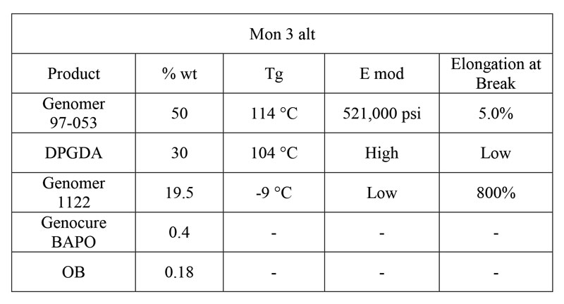
Hard SPF: Mon 3 Alt
The first 3D SPF is for a general purpose, high-definition hard object. It is composed of epoxy methacrylate oligomer Genomer 97-053, which provides the high Tg, high E mod oligomer base; DPGDA, a powerful diluent that also has a very high Tg; and Genomer 1122, an aliphatic urethane monoacrylate diluent with extremely high elongation. The high elongation component is important to reduce some of the shrinkage stress and temper the brittleness of the other two components, while also reducing the viscosity of the formulation. The formulation is shown in Table 1.
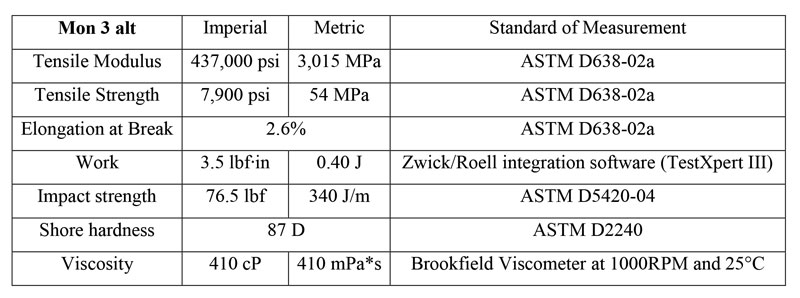
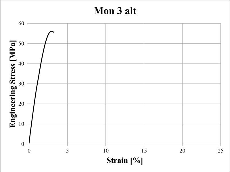
This general formulation has the stress-strain curve shown in Figure 1 and mechanical data in Table 2. Properties were measured according to ASTM D638-02a, on type VI and V dogbones. The formulation was printed on a Formlabs Form 1+ printer, using the Clear version 2 settings at 0.1mm, and post-cured for an hour on each side. The total post-cure dose delivered to each side was extrapolated to be 480 mJ/cm2 of UVA, with no appreciable emission in the UVB or UVC region.
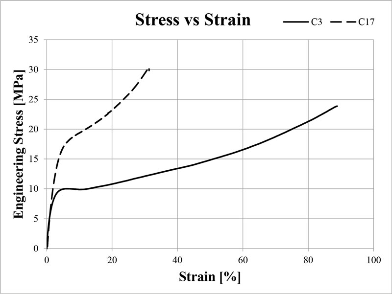
Tough SPFs: C3 and C17
The next two SPFs are for tough, engineering type applications. The definition of toughness is woefully imprecise in the 3D printing world, and most formulations need to be optimized for the specific application. However, the general properties of a tough formulation are high tensile strength, high elongation and high impact resistance.
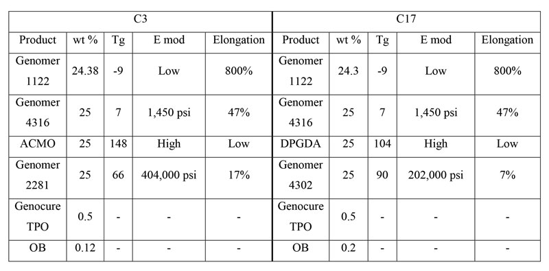
Toughness is academically measured by the area under the stress-strain curve – known as Work – and that is what these formulations strive to maximize, while keeping in mind the previous three considerations. The two formulations each consist of “chunks” of two hard, high E mod components and two soft, high elongation components. These components either provide the strength and rigidity to withstand high stress or provide the flexibility to deform with plastic flow, rather than shattering. This results in an object that is very difficult to deform but will stretch and bend significantly before complete failure. The two tough formulations, C3 and C17, are shown in Table 3.
Formulating for 3D printing is a new challenge, which proves that the energy curing industry is continually pushing the envelope of material properties, and formulators will need to grow with it to keep pace with diverse and demanding applications. With the help of new raw material development and innovative formulation problem-solving, the new requirements of 3D vat photopolymerization are completely achievable. The hope is that this paper can provide formulators with enough general background knowledge to begin working with this new technology, or to provide a new perspective on how to achieve mechanical properties comparable to engineering thermoplastics.
References
- Kainer, S. (2003). The oldest pottery in the world. Current World Archeology, 44-49.
- Hull, C. W. (1986). United States of America Patent No. US4575330 A.
- Schoffer, F. (2016, May 15). How Expiring Patents are Ushering in the Next Generation of 3D Printing. Retrieved from TechCrunch: https://techcrunch.com/2016/05/15/how-expiring-patents-are-ushering-in-the-next-generation-of-3d-printing/
- Jorgenson, D. W., Ho, M. S., & Samuel, J. D. (2014). Long Term Estimates of U.S. Productivity and Growth. Third World KLEMS Conference Growth and Stagnation in the World Economy. Tokyo.
- Deckard, C. R. (1997). United States of America Patent No. US5597589 A.
- Formlabs. (2016, June). The Ultimate guide to Stereolithography. Retrieved from Formlabs.com: https://formlabs.com/blog/ultimate-guide-to-stereolithography-sla-3d-printing/
- Webster, S. (2017, May). The Ultimate Guide to 3D Printing Thermosets for Manufacturing and Production. Retrieved from EnvisionTec.com: < a href=”https://envisiontec.com/ultimate-guide-3d-printing-manufacturing-production/” target=”_blank”>https://envisiontec.com/ultimate-guide-3d-printing-manufacturing-production/
- Charlesworth, S. (2016, May 16). Bits to Atoms: How Carbon’s CLIP 3D printing technology works. Retrieved from Tested: < a href =”http://www.tested.com/tech/3d-printing/570369-bits-atoms-how-carbons-clip-3d-printing-technology-works/” target=”_blank”>http://www.tested.com/tech/3d-printing/570369-bits-atoms-how-carbons-clip-3d-printing-technology-works/
- Adzima, B. (2015, February 10). How to tune Ember’s print setting for new resins. Retrieved from Instructables: < a href=”http://www.instructables.com/id/How-to-tune-Embers-print-settings-for-new-resins/” target=”_blank”>http://www.instructables.com/id/How-to-tune-Embers-print-settings-for-new-resins/
- Adzima, B. (2015). The Ember Printer: An open source for software, hardware, and materials development. UV/EB west 2015. Redondo Beach: RadTech
R.J. Viereckl is a chemist working in the application lab of Rahn USA, specializing in SLA/DLP 3D printing, UV curable pressure-sensitive and laminating adhesives, and in UV curable coatings. He graduated from Northern Illinois University in May of 2017 with a B.S. in Chemistry. For more information, contact Viereckl atrudolf.viereckl@rahn-group.com or visit www.rahn-group.com.


