


By Geri Tangdiongga, Don Moncy Dominic and Dominik Stephan, Dymax Asia Pacific Pte. Ltd.
Abstract
Ultraviolet (UV) LED technologies are progressing very rapidly in recent years, both in performance and cost. Therefore, the measurement equipment and methods for UV LED curing systems must be well understood. This paper focuses on the measurement and characterization of the UV LED curing systems, particularly in the UVA range. Moreover, the risks and safety concerns of UV will be discussed, with a focus on illuminating the inherent advantage of LED.
Introduction
In recent years the demand to incorporate UV LED in curing systems – instead of conventional UV lamps – has increased significantly. Although applications using UV sources still are dominated by conventional UV lamps, it was reported by Yole Développement that the forecast of market share of the UV LED has increased from 19.1% in 2014 to 41.4% in 2019.1 Furthermore, the total market size of UV LED has increased from $20.2 million (US) in 2008 to $127.0 million in 2015 and was predicted to have further increased to $505.5 million in 2019. Consistent with Yole Développement’s report, the study done by Allied Market Research showed that the global UV LED market size is expected to reach $1.2 billion by 2026, from $271.1 million in 2018, growing at a CAGR of 17.3% from 2018 to 2026.2 UV curing – such as inks, coatings and adhesives applications – accounts for nearly 60% of UV LED’s market size, and more than 50% of the users are in Asia.
UV curing is a process of utilizing UV energy to initiate the photochemical reaction that generates a crosslinked network of polymers. The strong growth of UV LEDs is mostly determined by the attractiveness of the technology over conventional UV lamps. Some of UV LED’s advantages are discussed below:
Compactness
UV LED can be utilized in system surface mounted device (SMD) package form or in die form factor, using chips on board (COB) technology. As a result of its “flexibility,” the design of the UV LED emitter for the curing system becomes compact. Different types of curing systems, such as flood, spot or modular systems, can be designed. This flexibility is difficult to achieve if the curing system utilizes traditional UV lamps. For example, consider an end-of-wand, spot-based UV curing system: A UV lamp-based UV curing system needs a long guide to divert the light into the spot, making the system appear bulky, while the UV LED-based curing system can be designed in such a way that it uses only an aspheric lens to converge the light, resulting in a simple and compact design with higher efficiency output.
Longer product lifetime
The typical lifetime of conventional UV lamps is about 2,000 hours or up to 8,000 hours for microwave UV lamps, while the UV LED’s life is usually reported to be in the range of 20,000 hours.3 Typically, UV LED manufacturers follow the test standards (LM-80 and TM-21) that are applied to the visible wavelength LEDs to determine the lifetime. The lifetime of the UV LED is defined as the number of operating hours until the degradation of output reaches the defined level, noted as Lp, where p is the percentage of the initial output power. In visible LED, L70 is commonly used to determine the lifetime of LED. A longer lifetime of the light source in the system is beneficial for the end user because of its longer replacement cycle, less downtime for the system and greater stability over time. The lifetime can be extended if the UV LED system is operated under intermittent mode. Furthermore, the lifetime of the light source depends highly on the driving current, as well as device and environment temperature. Currently, the technology of UV LEDs in the UVA region is more advanced and mature compared to that of UV LEDs operated in the UVB and UVC region. When the UV LED is integrated into the system – for instance, emitter and curing system – the lifetime of other parts must also be considered. Therefore, the rated lifetime of the UV LED systems, such as UV light curing systems, will be shorter at the UV LED package level compared to the system level. Hence, the actual lifetime should be determined as use-condition in the application. However, the root cause of the system’s failure is often due to the environment, the auxiliary system design4 and the possibility that the end user does not follow the system’s installation requirement.
Environmentally friendly (i.e. ozone and mercury free)
The UV lamp’s emission spectrum shows multiple peaks spreading from UVC to the visible spectrum. At the short wavelength, which is typically from 160 to 240 nm, the UV light can convert the oxygen into ozone (O3). The produced ozone can be a health issue if it is inhaled for prolonged periods. Therefore, it is suggested that the ventilation system surrounding the process should be set up properly to reduce risk. Furthermore, some conventional UV curing systems use mercury-based UV lamps as the emitter. Mercury contamination can occur if the UV lamp is broken. Hence, safety instruction is necessary to handle the breakage of mercury-based UV lamps. UV LED’s emission has a single peak, with the typical bandwidth of 9 to 15 nm, which can be selected. Doing so avoids the wavelength ranges that can produce ozone, especially for curing applications utilizing UV light at UVA and UVB bands. Additionally, the UV LEDs are made of semiconductor material (InGaN type), which is much safer and does not contain harmful materials or complicated disposal procedures.
On top of the above-mentioned points, there are additional benefits supporting environmental friendliness: less electrical power consumption, no warm-up time, immediate performance availability and ease of maintenance, with fewer service intervals.
With the increased demand for UV LED for curing applications, end users gradually shift from UV lamp-based curing systems to UV LED-based systems. While there are many advantages to using UV LEDs over UV lamps in curing applications,5-8 there still are some technological challenges in performance and remaining safety risks that UV curing system integrators, metrology device providers and end users will encounter. For instance, the end user must study and carefully match the adhesive and the UV LED system in terms of the adhesive’s absorption and the LED’s wavelength. The end user needs to characterize the system by evaluating peak irradiance, energy and curing time needed to achieve the optimized curing process.
Another key challenge involves the proper measurement method of output for curing applications from the UV LED system. With the proper method and measurement tools – such as a UV radiometer – the output of the UV curing system can be measured accurately. This measurement of output in the manufacturing line is highly recommended for production consistency. The measurement is aimed:
- To ensure reliable application performance
- To ensure repeatability and stability of the curing process
- As a preventive measure to monitor the degradation of the curing system
Therefore, this report aims to give an overview and recommendations to the end users of UV LED curing systems – such as experienced process engineers, manufacturing engineers and technicians – on the performance measurement of UV LED curing systems using an appropriate radiometer. The report also covers the risks and safety concerns in operating UV LED curing system.
UV radiation and safety concerns
UV radiation is in the form of electromagnetic waves, with wavelength range between x-ray and visible light (10 to 400 nm). Sources of UV radiation can be natural, like the sun, or artificial, such as mercury-vapor lamps, black lights, metal-halide lamps, UV LEDs and UV lasers. Based on its wavelength range, the UV radiation can be classified into:
- UVA: 315 to 400 nm
- UVB: 280 to 315 nm
- UVC: 180 to 280 nm
- Vacuum/extreme UV: 10 to 180 nm
Although there are negative effects of UV radiation on human health and the environment (ozone creation), UV radiation also can be beneficial for our lives.9 It can be a source of Vitamin D. In industrial and medical applications, UV radiation is widely used in curing polymers and ink, as well as in medical phototherapy treatment, forensic analysis, water disinfection, sterilization of certain viruses, horticultural lighting for optimal photosynthesis, etc.
This section discusses the safety of using UV in curing applications. Applications in adhesive curing, typically utilize radiation in the UVA region because a majority of the polymers and inks can only be cured by UVA due to the specific properties of the photoinitiator used in the formulations. The biggest hazard of the conventional UV lamp-based system is the UV radiation from the emitter. Being exposed to excessive UV radiation can be dangerous for humans. UV radiation, especially in the UVA and UVB spectra, can lead to cataract and other eye diseases, skin cancer, sunburn and accelerated skin aging. There also is evidence that UV radiation reduces the effectiveness of the immune system8. The curing systems available in the market use conventional UV lamps as the source, and these lamps emit not only in UVA but also UVB and some visible spectra.
However, using a UV LED system is inherently safer: The emitter’s wavelength is controlled in the UVA region, with a narrow bandwidth. Thus, from a safety perspective, the risks of UV LEDs are more manageable with simple precautions.
When it comes to the maximum value of UV exposure, most authorities follow the UV exposure threshold limit values (TLVs) recommended by the American Conference of Governmental Industrial Hygienists (ACGIH). The recommended TLV value for the UVA wavelength region (315 to 400 nm) should not exceed 1.0 mW/cm2 for a period greater than 1,000 seconds (approximately 16.7 minutes), and for exposure time less than 1,000 seconds, the total energy should not exceed 1.0 J/cm2. To put it into perspective, 1 mW/cm2 is the typical intensity level in a cloudless spring day in New England, measured using a radiometer that is pointed directly at the sun.10
Effects on the eye
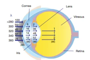
UV exposure to eyes has been associated with cataract and retinal degeneration. The cornea and intraocular lens are the most important tissues of the eye to absorb UV radiation. As reported by Walsh,11 the cornea absorbs the most UVB (below 300 nm), and the intraocular lens absorbs UVA (below 370 nm), as illustrated in Figure 2. It is, therefore, recommended that users wear UV grade eye protection when operating a UV source or while in close proximity to the UV curing system. The safety eye protection must be qualified under the OSHA and ANZI Z87.1 standard. For UV radiation protection, the safety eyewear code is indicated in letter “U” followed by a number on the scale 2 to 6, with 6 being the lowest transmission of UV radiation through the eyewear. It is advisable to consider the following factors in choosing the appropriate safety eye protection: (1) the ability of the safety eyewear to protect against specific workplace hazards other than UV radiation, (2) provision of unrestricted vision and movement and (3) any interference with or restriction of the function of any other personal protection equipment the employee wears.
Besides safety eyewear, a protective shield also can be used as protection to minimize the end user’s exposure to UV, since the UV emitter in the curing machine might emit stray radiant energy away from the application surface. The possibility that stray radiant energy can leak is high because it can arise from the reflection on various surface materials and improper installation or design of the system. The UV protective shield can be made of black anodized or black coated metal sheets, rigid plastic films – typically acrylic and polycarbonate – or flexible films, such as UV blocking flexible urethane film.12 Plastic materials melt at very low temperatures compared to metals, so the shields made from acrylic or polycarbonate materials must be used at a sufficient distance from the source to overcome the heat generated by UV sources – especially conventional UV lamps – to avoid any form of softening.
Effect on the skin
The effects of UV radiation on skin can be classified into two categories; acute, with effects appearing within a few hours of exposure, and chronic, with long-lasting and cumulative effects, which may not appear for years. An acute effect of UV radiation can appear as redness of the skin: erythema or sunburn. Chronic effects include accelerated skin aging and skin cancer. Furthermore, UVB radiation’s effect in skin tissue is associated with the skin burning, which increases the likelihood of developing skin cancer13. The effect of UVA radiation, which penetrates deeper into the skin tissue, is associated with premature skin aging and can also lead to skin cancer.13,14
To protect the skin from UV radiation, appropriate gloves and coats are recommended for end users. Glove materials such as nitrile, latex or tightly woven fabric are suitable to protect the skin against large amounts of UVA and UVB. Dark and shiny finishes also can prevent UV radiation from penetrating the skin by absorption and reflection, respectively. These types of gloves have low UV transmission compared to vinyl-based gloves. During the operation of UV devices, wearing a long-sleeved coat is recommended to ensure that the skin is not exposed to UV radiation.
To mitigate the risks of UV radiation exposure, control measures must be designed carefully to minimize exposure to eyes and skin and to prevent cumulative exposure. The precautions needed depend on the risk assessment. If end users are unsure about the quality of the UV curing system’s safety equipment, they should use a UV meter/radiometer to measure stray radiant energy at the location of interest. The measurement of UV using a radiometer is discussed in next section.
As discussed, UV LED sources are inherently safer to operate than conventional UV sources. However, an important element in eliminating the risk of UV radiation exposure is training and awareness for end users.
Guideline for measuring UV LED curing system
The quality and consistency of the end result in the polymerization of an adhesive depends on many factors. One factor is the stability and consistency of the UV output, including the radiant power or irradiance. It is important that the output of the curing system is checked and monitored regularly to ensure its power or irradiance value is maintained at the desired level. This section will provide guidelines for measuring the UV curing system – especially for the UV LED-based curing system.
Optical parameters of UV LED curing systems
Generally, basic optical parameters of UV LED curing systems consist of:
a. Peak wavelength
The wavelength emitted from UV LED is controlled by the selected/engineered semiconductor and doping materials.15,16 Unlike conventional UV lamps, the emission of UV LEDs has a “reasonably monochromatic” spectrum (or rather one peak) with specific peak wavelength and relatively narrow bandwidth, typically between 9 to 15 nm, compared to visible LED bandwidth. A spectrometer is required to characterize the wavelength parameters of the UV LED curing system.
b. Peak irradiance
Irradiance is a measurement indicating the intensity of the radiant power emitted from a UV LED onto a specific application surface. It is expressed in units of W/cm2 or mW/cm2. Irradiance decreases exponentially with increasing distance. In the specification of a UV LED curing system, peak irradiance value is used as a key parameter. Per definition, peak irradiance is the highest irradiance at a point of reference measured by a light meter or a radiometer. Datasheets of UV LED curing systems often indicate the measurement location of peak irradiance at the emitting window or at a specific distance from the emitting window. However, some datasheets do not indicate the exact measurement location in terms of distance and lateral position – for example at the center, edge or corner of the referenced area. This results in confusion for the end user and might void effective datasheet performance comparisons.
c. Energy density
Energy density measurement is the collection of the irradiance over a specific time and is expressed in Joules per square centimeter (J/cm2). In a conveyor system, the measurement of energy density is often used as a parameter to determine the UV cure ability. The end user can adjust the speed of the conveyor to set the correct energy density while the source emits the constant intensity.
d. Uniformity
Another important parameter is the uniformity of the UV distributed over specified locations. Not all UV curing systems emit consistent energy across the entire curing area. Uneven distribution can lead to poor adhesive curing quality or even lack of cure. Uniformity is the variation of energy distribution on the specified distance and area. It is measured as a ratio between highest and lowest irradiance values in the area of interest and expressed in percentage. To establish process uniformity, end users can adjust the measurement location during measurement and tune the UV curing system accordingly.
Further important parameters that are not highlighted in this paper are the operating and ambient temperature. As mentioned in the earlier section, UV LEDs are temperature-sensitive devices.17,18 The output power decreases as the function of the temperature, hence the lifetime of the emitter will be reduced. The UV LED curing system needs to be placed and operated based on the manufacturers’ instruction for the cooling mechanism in the system to operate at maximum capacity.
In the following sections, the guidelines on measuring the irradiance of UV LED curing system using a radiometer are explained.
Radiometer as a measuring device
As mentioned in the previous sections, a radiometer is used to measure irradiance values at a given location and distance. It is a useful device to monitor and ensure a stable UV curing process. A radiometer also can be used for:
- Maintaining a reliable UV curing process
It can ensure that a UV curing system is providing good irradiance and dosage levels required for successful curing. - Acting as a safety measurement tool during the UV curing process
Radiometers are sufficiently sensitive to measure the intensity of stray or reflected energy. - Measuring transmission rates through substrates
It measures the transmission rates of various wavelength ranges through substrates that sometimes absorb various frequencies of energy. To ensure an effective curing process, it is critical to measure the intensity reaching the cure site below any intervening substrate.
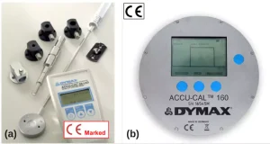
Based on the form factor and application, the radiometers available in the market can be classified into handheld/end-of-wand and disc/puck type. For manufacturing lines, it is necessary for the design of both types to be compact and easy to operate. Handheld types of radiometers are suitable for spot and end-of-wand curing system configuration. Often, they come with adapter kits to fit into the light guide or connector of the UV curing system. The puck-based radiometer is more suitable for measuring irradiance or energy density in conveyor and flood chamber UV curing system. Figure 3 shows the example of Dymax’s UV radiometers.
In selecting a suitable radiometer for a curing application, several factors need to be considered to get accurate and repeatable measurements:
The Emitter of the UV curing system
The emitter is the UV source part in a curing system. It can be designed using conventional UV lamp or UV LED. Typically, the UV emitter consists of the energy source, additional optics in form of reflector, lens or UV grade optical window, and a thermal system in form of air or liquid cooling mechanism. All sources emit UV but in different spectral ranges. The conventional UV lamps have a wide spectral range across UV spectrum and small portion in the visible spectrum, while UV LEDs emit radiant energy in the narrow UV spectral range. The end-user should know that different tools might need to be used to measure the irradiance or energy of the conventional UV lamp and UV LED. Radiometers for a UV broadband lamp can only measure the conventional UV lamp-based curing system and cannot be used to measure a UV LED curing system because they measure one a particular wavelength range. For measuring a UV LED system, a specific measurement tool tuned for this use case is recommended.
Responsivity of a radiometer’s detector
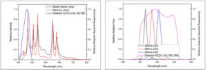
The key parameter in selecting a radiometer is identifying the wavelength of the emitter’s source. It is extremely important that the spectrum of the emitter’s source is within the spectral responsivity of radiometer’s detector. However, a radiometer for conventional UV lamps shall not be used to measure the UV LED lamps due to the different range of quantifying the radiant energy. While it is desirable that the radiometer’s detector has flat top responsivity over UV spectrum, such a detector would be very costly and would not be handy, hence it is not usually applied in industrial applications. For applications in adhesive curing using UVA, such as metal halide and mercury lamp, the detector used has highest responsivity at 360 to 365nm because the spectrum of UV metal halide and mercury lamp has a higher peak at that range, as depicted in Figure 4.
For a UV LED-based curing system, it is recommended that the end users understand at which wavelength the radiometer is calibrated. Various types of radiometers can be used to measure irradiance and dosage at single or multiple wavelengths. If the radiometer’s measurement mode is tuned at 385 nm but is being applied to measure irradiance of the UV LED curing system, which has a peak wavelength at 365 nm, the measurement result will not be reflected as the true value and can only be assumed as a relative value. This still can be used for process stability analysis. Simple measurements are performed to find the difference in irradiance measured between specifically tuned radiometers. The set-up is constructed in such a way for the measurement to be reliable and repeatable. It is seen from the result in Table 1, at peak wavelength of 365 nm, that the deviation measured using two radiometers is about 13%.
Spot and flood UV curing system
Another important factor in achieving accurate results is the ability of a radiometer to measure spot and flood type UV curing systems. The emitter of a UV spot curing system is coupled with a light guide or collimated lens, resulting in a focused and narrow output beam. The spot-type curing system is typically used to cure small parts with high intensity, thus it provides faster curing time. Unlike the spot curing system, the flood curing system is used to cure a larger part or small parts at the same time. To measure the irradiance of the UV curing system, the end user should ensure that the emitter and radiometer’s detector are in parallel position. A slanted or tilted radiometer sensor will cause an inaccurate measurement. To measure the irradiance value of the spot curing system, the radiometer is attached perpendicular onto an adapter that fits the aperture of the light guide or connector. The adapter and connector must be designed accurately so that the total radiant energy illuminates the entire detector window without loss. It also must be uniform across the measurement window. Some radiometer manufacturers provide standard and customized adapters and connectors or a measurement mode specifically designed to measure the UV in flood mode or certain spot sizes.
Lateral position and vertical location during measurement
At a production line, the radiometer is used to monitor the output of the UV curing system with the goal of ensuring the system operates within the specification. For that reason, a consistent irradiance value is desired. Because the irradiance measured is distance-dependent, to achieve repeatable and consistent measurements, the location and the orientation must be equal at each measurement. Furthermore, not all flood systems emit consistent energy laterally, which results in different irradiance values across the illuminated area. For this reason, the uniformity must be determined at working distance to achieve good and repeatable curing results.
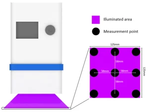
Few measurement points across the illumination area can be taken using the radiometer to map the irradiance uniformity, as illustrated in Figure 5. If the irradiance map is constructed, the dimension of an effective curing area can be determined and matched to the curing application.
Temperature
All semiconductor-based devices are temperature sensitive. In general, the operating temperature of the radiometer should not be more than 70°C. If the temperature of the UV curing system is built up with long exposure of UV radiation on the detector, the performance of the detector starts to attenuate.19,20 Current technologies enable radiometers to perform the irradiance or energy density calculation at the milliseconds interval to avoid temperature error. Additionally, when the UV emitter turns on, it is recommended that users measure its irradiance after the temperature reaches a steady state to ensure the reading is consistent and accurate, and ensure that the radiometer has cooled down before performing the next measurement. One of the advantages of using a UV LED-based curing system is its shorter warm-up time in comparison to the conventional UV curing system.
Radiometer calibration and maintenance
Components of the radiometer will deteriorate over time, resulting in reduced measurement accuracy – even more with frequent use. The radiometer is a delicate system, particularly its optical parts. Slight changes or debris in the optical parts can affect results significantly. Therefore, periodic maintenance and calibration are recommended, including cleaning and proper storage.
Periodic calibration of the radiometer is necessary to maintain the lowest possibility of error. During calibration, the error of all important parameters is determined. The calibration process is usually performed on a standard artifact, traceable to national standards, and measured under defined environmental conditions. Most calibration laboratories follow the standard set by National Institute of Standards and Technology (NIST). The result and associated measurement uncertainties are recorded on a calibration certificate. The key factor in the calibration process is that it should display an unbroken chain of transfer comparisons originating at a national standards laboratory through the final products of the radiometer.21
Conclusion
The market share of UV LED-based curing systems is expected to continue increasing every year as the technologies become more mature. The inherent advantages of UV LEDs over the conventional UV bulb are not only due to performance but also environmental friendliness and safety. Some end users may not yet employ the proper methods to measure the output using a radiometer, which can lead to false measurement results that may seem correct or close to the desired value. An appropriate measurement method for the UV LED curing system is needed to ensure consistency of the result as well as to eliminate the risks of using UV. Furthermore, it is important to evaluate data in a UV curing system datasheet that does not list radiometer type, the location where irradiance is measured and means to couple the UV energy to the detector. This report can be utilized as a guideline for end users to obtain accurate and repeatable measurements of a UV LED curing system – especially those measurements using a radiometer.
Disclaimer
Technical data provided is of a general nature and is based on laboratory test conditions. Dymax does not warrant the data contained in this bulletin. Any warranty applicable to the product, its application and use, is strictly limited to that contained in Dymax’s standard Conditions of Sale. Dymax does not assume responsibility for test or performance results obtained by users. It is the user’s responsibility to determine the suitability for the product application and purposes and the suitability for use in the user’s intended manufacturing apparatus and methods. The user should adopt such precautions and use guidelines as may be reasonably advisable or necessary for the protection of property and persons. Nothing in this bulletin shall act as a representation that the product use or application will not infringe a patent owned by someone other than Dymax or act as a grant of license under any Dymax Corporation Patent. Dymax recommends that each user adequately test its proposed use and application before actual repetitive use, using the data contained in this bulletin as a general guide.
References
- Yole Développement, UV LEDs: Technology, Manufacturing and Application Trends, 2014.
- Allied Market Research, UV LED Market Report, 2019.
- F.J.Arques-Orobon, N.Nuñez, M.Vazquez, C.Segura-Antunez, and V.González-Posadas, “High-power UV-LED degradation: continuous and cycled working condition influence,” Solid-State Electronics, vol. 111, pp. 111-117, Sep 2015.
- Phoseon Technology, “UV LED System Lifetime,” Hillboro, OR, USA, 2017. Accessed on Dec., 15, 2019. [Online]. Available: https://phoseon.com/industrial-curing/technology/led-uv-system-lifetime.
- D. Leonhardt et.al., “Advancements in UV LED technology and its impact on UV curing applications,” in Proc. of 13th International Conf. on Radiation Curing in Asia, China, 2013.
- S.L.Mcdermott, J.E. Walsh and R.G. Howard, “Comparison of the emission characteristics of UV-LEDs and fluorescent lamps for polymerisation application,” Optics and Laser Technology, vol. 40, pp. 487-493, 2008.
- V. Landry, P. Blanchet, G. Boivin, J.F. Bouffard, and M. Vlad, “UV-LED curing efficiency of wood coatings,” Coatings, vol. 5, pp. 1019-1033, 2015.
- K.C. Anyaogu, A.A. Ermoshkin, D.C. Neckers, A. Mejiritski, O. Grinevich, and A.V. Fedorov, “Performance of the light emitting diodes versus conventional light sources in the UV light cured formulations”, Journal of Applied Polymer Science, vol. 105, pp. 803–808, 2007.
- UNEP, ILO, and WHO, UV Radiation: environmental heath criteria 160, Geneva, Switzerland, 1994. Accessed on Dec., 15, 2019. [Online]. Available: http://www.inchem.org/documents/ehc/ehc/ehc160.htm.
- Dymax Corporation, Guidelines for Exposure to Ultraviolet Light, Torrington, CT, USA, October 13, 2010. Accessed on Dec., 15, 2019. [Online]. Available: https://www.dymax.com/images/pdf/literature/lit023_guidelines_for_uv_exposure.pdf.
- K. Walsh, “UV radiation and the eye,” Optician, vol. 237, pp. 26-33, 2009.
- Dymax Corporation, Dymax UV Light Curing System Safety Consideration, Torrington, CT, USA, October 13, 2010. Accessed on Dec., 15, 2019. [Online]. Available: https://www.dymax.com/images/pdf/technical_bulletins/lit133_dymax_uv_curing_systems_safety_considerations_tb.pdf
- WHO, Ultraviolet Radiation as Hazard in the Workplace, Geneva, Switzerland, 2003. Accessed on Dec., 15, 2019. [Online]. Available: https://www.who.int/uv/publications/en/occupational_risk.pdf.
- S. K. Jain and N. K. Jain, “Multiparticulate carriers for sun-screening agents,” International Journal of Cosmetic Science, vol. 32, no. 2, pp. 89-98, 2010.
- Y. Muramoto, M. Kimura and S. Nouda ,“Development and future of ultraviolet light-emitting diodes: UV-LED will replace the UV lamp,” Semiconductor Science Technology, vol. 29, pp. 084004, 2014.
- J. Heathcote, UV-LED Overview Part I — Operation and Measurement, RadTech Report, July/August, 2010, pp. 23-33.
- J. Heathcote, State of UV LED Curing Applications, UV+EB Technology, issue 1, 2019, pp. 18-22.
- P. Mills and J. Raymont, The UV-LED Paradigm Shift, RadTech Report, issue 2, June, 2013, pp. 43-48.
- J. Raymont and A. Kashyap, Measuring the Output of Ultraviolet Light Emitting Diodes, RadTech Report, issue spring, 2011, pp. 18-23.
- J. Raymont, “Radiometer-best of intentions,” SGIA Journal, vol. 6, no. 3, pp. 39-47, 2002.
- “Gigahertz-Optik‘s Calibration Laboratory for Optical Radiation Measurement Quantities,” 2019. Accessed on Dec. 15, 2019. [Online]. Available: https://www.gigahertz-optik.de/en-us/service-and-support/knowledge-base/calibration-laboratory-measurement-quantities.


