While electron beams are complex machines to build, the day-to-day operation of an EB is quite straightforward. Despite the wide array of possible applications, there are only a few settings to adjust: dose, accelerating voltage and line speed. That’s it! Now, understanding how these parameters and the throughput of the beam apply to achieving a well-cured coating or a sterilized surface might take a few additional paragraphs …
Dose is defined as the energy absorbed per unit mass. Common units for dose are kilogray (kGy) and megarad (Mrad), where 10 kGy = 1 Mrad = 10 kJ/kg. The term dose sometimes is used in the UV vernacular as a synonym for exposure or effective energy density; however, it is important to note that this usage is not in agreement with the EB, or more broadly, the ionizing radiation definition of dose.1 In machine parameters, dose (D, kGy) can be defined as
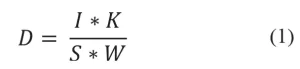
where I is the beam current (mA), K is an efficiency factor, S is the line speed (mpm) and W is the beam width in vacuum (m).2
For the EB operator, though, dose simply is the setting that determines material effects. Too little dose and that wet, EB-curable coating won’t fully polymerize, and it will emerge from the beam still wet. Too much dose and that same coating will emerge dry but crackled like dried mud – the additional energy causing so many cross-links the coating becomes brittle. Similarly, the dose can be adjusted to add just the right amount of heat resistance to polyethylene or to achieve a log-10 reduction in a particular microbe.
Typical dose ranges for common applications include 25 to 50 kGy for the curing of inks and coatings, 50 to 150 kGy for cross-linking plastics and 10 to 35 kGy for sterilization of products. Once dose and line speed settings are selected, the EB operating system does all the hard work. Using Equation 1, it calculates the required beam current, and it even ramps the beam current along with the line speed to make sure the product receives a consistent dose during start-up and shutdown of the line.
Where dose determines the effect on the irradiated material, accelerating voltage (kV) determines how deeply into the material the dose is delivered. The cross-linking of polyethylene (PE) is a great example of how voltage selection can be used to achieve different results for different applications. For instance, in the case of shrink films, uniform dose distribution is desired to achieve uniform material properties throughout the film. The desire in heat seal applications, in contrast, is to only cross-link the outer layer of PE. The inner layer of the film must obtain little to no dose in order to prevent any increase in the melt temperature, ensuring a good heat seal. The needs of each application can be met by merely adjusting the accelerating voltage.
It should be emphasized that dose and accelerating voltage are independent dials. A dose of 30 kGy can be delivered at 80 kV or 300 kV or any voltage in between, as can a dose of 50 kGy, 100 kGy or any dose achievable by the EB. This independence provides great flexibility in application development.
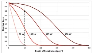
The voltage required to penetrate a material is dependent on two factors – the material density and the material stopping power. Unlike UV, the penetration of accelerated electrons is not affected by the optical clarity of the material. Monte Carlo simulations are used to model how the electrons will interact with a material and to create depth-dose curves (Figure 1).
Relative dose is shown on the vertical axis, where 1 represents the total surface dose. The horizontal axis consists of the depth of penetration into the material. The units are a bit odd for a depth – g/m2 – but it is written as such to be applicable for use with different material densities. If the density of the material is 1 g/cm3, the units of depth become micrometers (µm). The example illustrated on the graph with dotted lines would read as follows for a material with a density of 1 g/cm3: 80% of the surface dose reaches a depth of 50 µm with a voltage setting of 125 kV. If the material density were 2 g/cm3, the depth would simply be revised to 25 µm.
Note: Monte Carlo simulations require information about the machine design, and thus the depth-dose curves generated are not universal. In addition, a representative material is usually chosen for modeling, and the curves should only be used to estimate voltage settings for similar materials – plastic for plastics, metal for metal, etc. – to avoid excessive error.
Finally, throughput. This variable is not an operator input but instead is tied to machine capacity. A throughput tells the operator what maximum dose can be achieved at a particular speed. The units of throughput are kGy*mpm or Mrad*fpm. With a throughput of 10,000 kGy*mpm, for example, the maximum dose at 100 mpm would be 100 kGy, at 50 mpm the maximum dose would be 200 kGy, and so forth. This relationship stems from Equation 1, which can be used to relate the maximum current rating of an EB power supply to dose and speed. Additionally, the throughput does vary with the accelerating voltage, because the efficiency factor, K, changes with voltage.
Crash course complete!
 Sage Schissel, Ph.D.
Applications Specialist
PCT Ebeam and Integration LLC
sage.schissel@pctebi.com
References
- Terminology Used for Ultraviolet (UV) Curing Process Design and Measurement. https://www.radtech.org/intro-to-uv-eb/uv-glossary
- Davidson, R. S., Mechanism of Electron-Beam Curing in Radiation Curing in Polymer Science and Technology. Fouassier, J. P., Rabek, J. F., eds. Vol.3. 1993.