


Did you know there still are electron beams in operation that were manufactured over 30 years ago? With relatively few moving parts and a solid industrial build, electron beams are prone to long lifetimes; however, true longevity, as with most machines, comes from establishing and performing good maintenance practices. By understanding a bit about how an EB functions and what consumable parts are critical to a well-functioning machine, you’ll be well on your way to peak EB performance!
The workhorse of every electron beam, and thus, the source of most of the routine maintenance, is the cathode and its surroundings. An example of a low-energy (≤ 300 kV), area-type electron beam cathode and its housing are shown in Figure 1. To generate electrons, an EB has filaments. These filaments are heated electronically to give off electrons through a process called thermionic emission (Figure1A). Filaments are a consumable part and need replacing approximately every 8,000 hours of runtime.
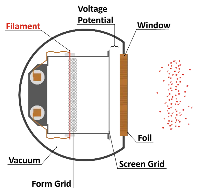
Area beams tend to be designed such that the filaments are placed incrementally across the width of the machine, equidistant from one another (Figure 1B). This design serves multiple purposes, including being easily scalable to wide widths (100+ inches) and good dose uniformity across the width of an EB. Additionally, the distance between filaments is short enough that if a single filament is lost, the two on either side can compensate and dose uniformity still is adequate for running production. When a filament is lost, a fault appears on the operator screen. This is a good time to plan a maintenance day in the near future, as losing one filament typically is an indication more will break soon, especially if the filaments are near or have exceeded 8,000 hours. If multiple filaments are lost, a higher-level fault will appear on the screen and the EB will be prevented from running.
Once the electrons are generated by the filaments, they are spread and oriented using grids (Figure 1A), then accelerated via a voltage potential through a copper window and titanium foil. The copper window is needed to support and cool the foil and has hundreds to thousands of small holes that allow the accelerated electrons passage from the cathode through to the foil. The foil must be thin (≤ 15 µm) to minimize energy loss as the electrons pass through it to reach their intended target, be it coating, ink, film, etc. Titanium is chosen because the foil also must be strong to withstand the pressure difference between the cathode area under high vacuum and the reaction area at atmospheric pressure (Figure 1C).
The foil is another regularly consumable part. It has an expected life of four to six months, depending on a few different factors, such as the beam settings, number of run hours in that time span and cleanliness of the machine. Foils weaken over time due to the stress (vacuum) and heat (electrons) they experience. A degradation in the vacuum level may be a symptom of a weakening foil. Leaks in the foil too small to see can be identified by spraying the foil with isopropanol and watching for the vacuum levels to jump when the location of the leak is sprayed. Electron beams generally operate with a vacuum level in the range of 10-7 Torr and should not be operated above 2×10⁻⁶ Torr to protect the filaments and avoid contamination in the cathode area. Once poor-enough vacuum levels are reached, the beam will fault and prevent operation until good vacuum is restored.
Because of the thinness of the foil, it is fairly delicate and does not have great puncture resistance. Therefore, care must be taken with it during installation, but also in normal operation. The gap between the foil and the intended target of the electrons (called the air gap) often is as small as a fraction of an inch. This gap is kept small to minimize energy loss of the electrons and nitrogen consumption in ink/coating applications; however, a small air gap means the foil is more susceptible to scrapes or punctures should there be a protrusion of some sort from the web/sheet as it goes through the beam or should a loss of tension make the substrate jump into the foil. When the beam is open for cleaning or threading of the line, the foil is exposed, and attention should be paid so as not to inadvertently scrape or puncture it.
The last regularly consumable part on an EB is an O2 cell. A good fraction, if not a majority, of electron beams run in a nitrogen-inerted atmosphere to prevent oxygen inhibition in ink and coating applications.1 The remaining oxygen is measured with an O2 sensor to ensure it stays below 200 ppm during production runs. Over time, generally about six months, the O2 cell in the O2 sensor becomes contaminated with oxygen and no longer reports accurate values. Signs an O2 cell is ready to be switched out include becoming stuck on a single value, no matter how long the nitrogen flow has been on or if the flow has been changed, or reading an impossibly low value, such as 2 ppm.
Replacement of the filaments, foil and O2 cell is part of the training received during installation of a beam. Because failure of these components could prevent production, it is advisable to have either EB operators or onsite maintenance personnel trained to ensure the beam is operational as quickly as possible. Service technicians from the EB manufacturer also are available but will require scheduling and travel time, which will delay operation.
Part 2 of this article will continue this discussion by addressing expected downtimes; the benefits of weekly maintenance, preventative maintenance and keeping good maintenance logs; and EB components that get replaced every several years.
References:
- Schissel, S., 2021. Comparing EB and UV: Common Questions. UV+EB Technology. (2).
Acknowledgements:
Rian Lewison, director of customer service at PCT Ebeam and Integration
 Sage Schissel, Ph.D.
Applications Specialist, PCT Ebeam and Integration LLC
sage.schissel@pctebi.com


