


By Gary Sigel, Dan Baumann, Oliver Hamann, Pam Abbott, Donovan Hensley, Miltec UV, Inc.
UV-based binders for lithium-ion (Li-ion) battery applications from Miltec first appeared in the literature as early as 2009 as a demonstrated “Environmentally Green Technology.” These UV binders did not contain the hazardous material NMP (N-methyl-2-pyrrolidone), which poses a significant health risk. The UV process also significantly reduced electrode manufacturing costs by offering reduced drying requirements, minimal solvent recovery, a smaller footprint and lower overall capital costs.
In this article, the types of UV chemistries used to prepare UV binders will be reviewed along, with end-product testing and the physical properties of UV binder films and cathodes for Li-ion batteries. Coin cell performance prepared from these newer UV binders for NMC811 active material also will be reviewed.
Current PVdF Binder in Li-Ion Batteries
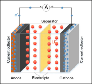
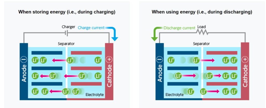
In its simplest form, a Li-ion battery is a device used to store energy by shuffling Li-ions between two electrodes. These electrodes, termed anode and cathode, are capable of storing lithium ions. Energy is stored and released as lithium ions travel between these electrodes through the electrolyte as depicted in Figures 1 and 2. 1, 2 In addition to the anode and cathode, a third component called a separator is placed between the electrodes. The separator electrically insulates the anode from the cathode but contains pores to provide a pathway for Li-ions to travel back and forth between the electrodes during charging and discharging of the cell.
The anode electrode consists of a thin conducting metal foil (usually copper) referred to as the current collector that is coated with a mix of anode material (typically graphite), binder and conductive carbon. The binder holds the particles in place and also adheres them to the current collector. The binder particles are typically carbon with particle sizes ranging from nanometers to microns.
Similar to the anode, the cathode is constructed from a current collector that is a thin metal foil of electrically conducting material such as aluminum and is coated with a mix of cathode active material, binder and a conductive additive. Cathode solid particles are held to the cathode current collector and to each other by a solid polymer binding material, which is typically polyvinyl difluoride (PVdF) that functions to retain adhesion and dimensional stability during charging and discharging cycles. Typical cathode active materials include particles of metal oxides such as lithium, cobalt, manganese, nickel or vanadium oxides, and other lithium compounds such as lithium iron phosphate. These materials are referred to as NMC – Nickel, Manganese and Cobalt as their principal components. The cathode active material is a source of Li-ions that migrate through the electrolyte to the anode during charging and migrate back to the cathode during discharge.
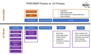
Today’s cathodes are manufactured using four steps to form the cathode coating; 1) dissolution of the binder PVdF polyvinylidene difluoride with NMP, 2) mixing carbon black and active cathode material to form the slurry, 3) application of slurry to the current collector, and 4) oven drying to remove the NMP (Figure 3). NMP has a high boiling point (202° C), is a VOC and is a health hazard. This makes the last step in cathode fabrication very costly from an operational standpoint due to the requirement of long ovens and solvent recovery systems to remove NMP.
A Greener State: UV Cathode Binders
The authors’ company’s UV cathode binder technologies are said to reduce the environmental impact, improve manufacturing speed and significantly lower the cost of battery cell manufacturing while offering competitive battery performance and cycle life. The company understood that going to a UV-curable binder system would result in substantial savings by replacing N-methyl pyrrolidone (NMP) with a lower boiling point and more environmentally friendly solvent to allow for faster line speeds and reduced footprint of equipment required.
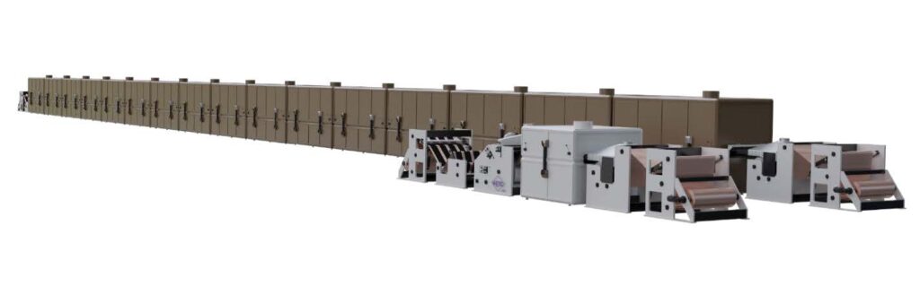
The process flow diagram in Figure 3 depicts the PVdF/NMP process Vs. UV Binder/Propyl acetate process. The PvdF/NMP process requires higher energy consumption due to the use of very large driers and complex solvent recovery system for NMP. The solvent recovery is dependent on the length of the oven for a specified line speed. As a result, a significant reduction in manufacturing footprint size is projected upon advancing from a PVdF binder to a UV binder as illustrated in Figure 4.
The UV binder process utilizes acrylated monomers and oligomers along with photoinitiators and additives that are further blended with a safe solvent, propyl acetate, with lower boiling point 102° C prior to mixing in active powders. The final slurry is applied onto the current collector typically by using a slot die coater and ran through a short oven to remove propyl acetate, calendared to meet porosity requirements and finally UV cured to allow for photopolymerization of the UV binder acrylate composition. 3 The UV photopolymerization occurring by the three-step process is comprised of the following:
- Initiation to form radicals from the photoinitiator,
- Propagation to form the polymer chain,
- Termination or depletion of the radicals in the system in the presence of UV lamps. 4
The depth of UV light absorption is dependent on the photoinitiator(s) extinction coefficients at a given wavelength for a given thickness of active cathode material/carbon filled UV cured binder. These UV binder slurries also can be acrylate polymerized by use of an electron beam to form the electrodes. This method of cure also works but can require more capital for equipment, installation, maintenance, safety X-ray monitoring and suffers from requiring nitrogen inerting and high KV accelerating energies to provide good electrode binder adhesive properties to the aluminum foil. 8
Entry into UV Binders For Cathode Electrodes
One of the first processes for manufacturing an electrode utilizing electron beam (EB) or UV radiation to cure electrode binding polymers to the active cathode materials and carbon and to the current collector is described in US patent 2011/0081565. 3 These early UV binder systems were based on a cross linked polymeric matrix formed from either methacrylated isoprene, methacrylated or acrylated polybutadiene functionalized rubber polymer in combination with a reactive acrylate diluents, wetting agent and/or photoinitiator. Examples of these first UV binder systems used in electrodes are given in Table 1.
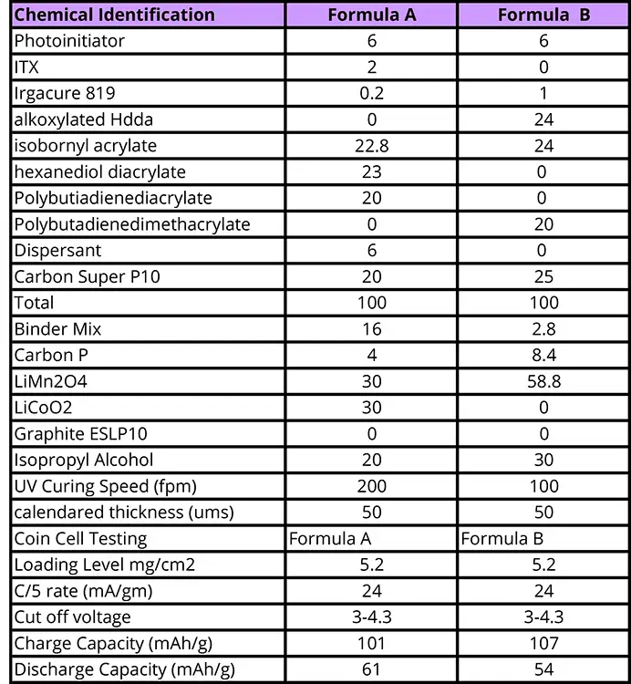
The UV binder system itself was further mixed with dispersants, Super P carbon and, finally, active material, and propyl acetate prior to processing. The UV binder slurry was applied to the current collector using a slot die coater. The final cathode electrode was UV cured using two MPI 600wpi D bulbs from 100-200fpm then calendared to 50 µm.
These first generations of methylacrylate or acrylate polybutadiene UV binder systems were found to exhibit good adhesion to the aluminum substrate as determined by folding and inverting the coated aluminum electrode to see if the cured cathode peeled away from the collector. Little swelling was found to occur as determined by minimum weight gain after two weeks at 140° F submerged in typical Li-ion battery electrolyte comprised of 40% ethylene carbonate and 60% dimethyl carbonate thus indicating that the UV binder is stable in a non-hazardous electrolyte.
Coin cells were prepared from final cathode electrodes. This first series of coin cells displayed charge and discharge properties at C/5 rate but performed poorly. Charge capacity ranged from 101 to 107 mAh/g and discharge from 54 to 61 mAh/g.
Second Generation of Cathode Materials
To improve upon battery performance, a second set of UV binders was prepared that incorporated commercial acrylate materials which were not available when the first set was prepared as well as improvements in processing to form the cathode electrode.
Two UV binders, C and D, were prepared for this study using acrylate-type materials at different amounts to give different mechanical properties. These formulations were comprised of multifunctional acrylates (MFA), polyurethane acrylate mixtures (PUA), polyester acrylates (PEA), monofunctional acrylates (A) that are diluents in PUA’s along with PI, dispersants, and propyl acetate solvent to cast films for UV curing and analysis (Table 2).
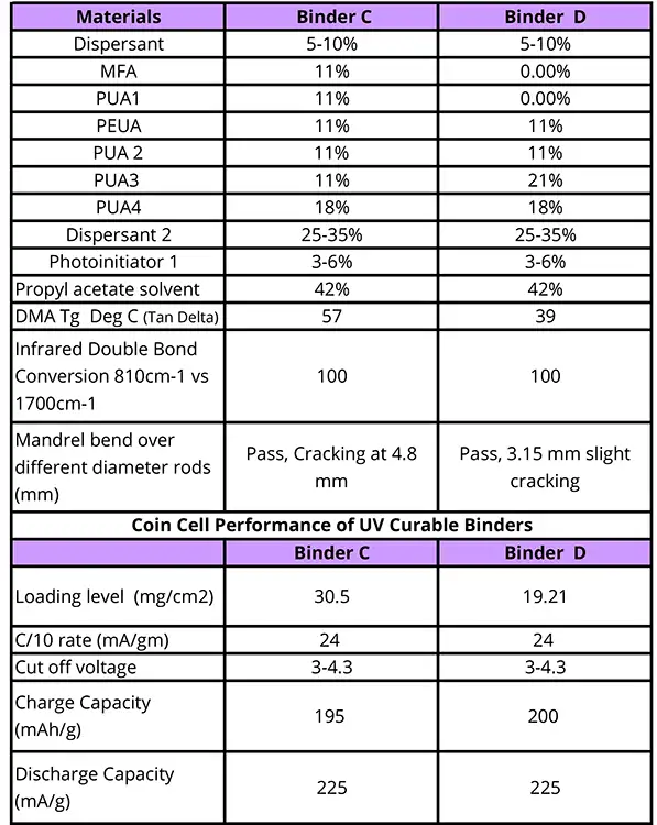

Glass transitions for the free films of these two formulations C and D using DMA analysis was determined to be 57° C and 39° C, as illustrated in Figure 5 for Tan Delta, Storage Modulus and Loss Modulus plots. Both Tan Delta curves are broad, which is presumed to be due to non-homogeneity of crosslink density as a result of differing polymer chain lengths as in the case of broad polydispersity that gives high values Mn/Mw. Only one distinct Tg was observed for Formulation D, but there appears to be a shoulder on the DMA curve for Formulation C at about 24° C.
The differences in Tg are attributed to completely removing the high functional acrylate MA1 (Tg > 100° C) and PUA1(Tg -5) in formulation C and replacing both components with equal amount of PUA3 (Tg -4) in formulation D.
Cathode electrodes prepare from these UV binders indicate that slightly better flexibility was achieved based on wrapping the electrode around a mandrel (collector face in) for the lower Tg 39° C formulation D. Values obtained for C and D were 4.8 mm cracking vs. 3.15 mm slight cracking, respectively.
Infrared analysis of films for formulations C and D indicates complete conversion of the C=C double bond to be 100% as there was no sign of an 810 cm-1 peak after UV cure in air.
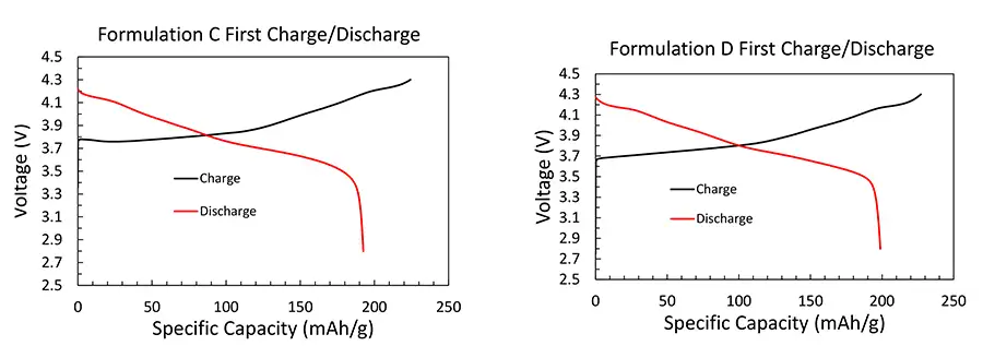
Cathode electrodes from these UV binders were used to prepare coin cells. Coin cells were subjected to cyclic charge and discharge at a rate of C/10 with a voltage window of 3.0 to 4.3 V. Both formulations exhibited excellent performance and characteristic voltage curves for NMC811 active material (Table 2, Figure 6). This represents a significant improvement in comparison to the first series of cathode electrodes. These results compare well with current coin cells made from PVdF binder.
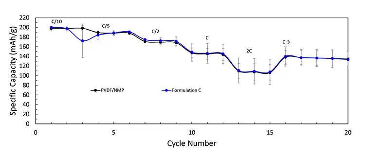
PVdF and UV-curable binders were tested in coin cells and compared. The charge and discharge rate (C-rate) was increased over the course of many cycles to access the rate capability of the binders. Figure 7 displays that the performance of each cell matches, indicating good battery performance. Mass loading, calendared density, and material ratios were kept the same in order to accurately compare the samples. High performance is critical to the adoption of UV-curable binder in the battery industry. Any new UV-curable binders must meet or exceed current PVDF performance in order to be considered for production.
Entry into UV-Curable Binders for Battery Separators
A separator provides a barrier between the anode (negative) and the cathode (positive) while enabling the exchange of lithium ions from one side to the other (Figures 1 and 2).
Conventional separators are comprised of thermoplastic layers of porous PE, PP or combinations that can lack the heat resistance required for Li-ion batteries. Heat generated during charging and discharging cycling or a localized short circuit can result in melting of separator layers that leads to melting and curling/shrinking of the separator. When this occurs, the anode and cathode can come into contact with each other resulting in a catastrophic failure. 6 In order to prevent cell failure, a ceramic coating is applied to the separator surface to reduce separator shrinkage during high heating events.
In 2014, the authors’ company had developed and began producing its first battery separator utilizing a waterbased UV binder/ceramic coating to give critical safety attributes of better thermal dimensional stability to prevent battery failure at temperatures above 180° C vs. conventional olefinic separators, as depicted in Figure 1.
Similar to the UV binder cathode, the UV-cured waterbased porous binder is basically a mixture of ceramic particles with monomers and/or oligomers. 3, 4 The ceramic waterbased slurry is further applied as a thin microscopic layer directly onto a 12 to 25 um microporous PE separator film to afford a final 2 to 4 um-thick, dry, protective coating.
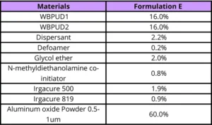
The pilot plant process involves application of the waterbased UV/ceramic slurry onto the polyolefin film web by use of a reverse-kiss gravure coater. Flashing off the water is accomplished by using a short IR dryer while film temperature is maintained by using a chill drum or plate. The UV binder/ceramic coated film is cured instantly by using a Miltec UV MPI-400 lamp to give the final structure depicted in Figure 7. One of the first waterbased separator binder formulations is given in Table 3 where the main components are two UV-curable waterbased dispersions, dispersants for the aluminum oxide powder and photoinitiator/amine package. 7
The three critical to quality (CTQ) attributes for a ceramic coated separator are air flow, shrinkage and porosity. To ensure that the coated olefinic substrate is porous enough to allow Li-ions to move across the separator, a Gurley test is performed that measures the resistance to air going through the noncoated PE porous film and coated ceramic film. A Gurley number is the time in seconds it takes for 100 cc of air to pass through one-square-inch of membrane when a constant pressure of 4.88 inches of water is applied. A low Gurley number indicates a high air permeability, high separator porosity and low roughness. The result of this test is value that indicates air resistance in units of seconds. Results of this test method show that the effect of the ceramic coating results in an increase in the Gurley value where the Gurley value for noncoated film is 68 sec and for ceramic-coated film is slightly higher (85 to 105 sec), depending on thickness of the ceramic layer, nominally 2 to 6 µm. The percent increase being 25% to 55% increase in Gurley values, which is commonly observed.
Coated separators must have good dimensional stability at high temperature >120° C to prevent shutdown mechanisms of the battery. Above 120° C the pores of the olefinic film will close, thereby preventing a short between cathode and anode from occurring.
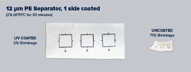
Dimensional stability can be determined by measuring the shrinkage of an insulator after exposure to a temperature of 170° C for 30 minutes. This is done by using a 5 cm square template to outline the area of the insulator film prior to exposure and remeasuring the size after exposure to calculate shrinkage. For example, the shrinkage of the noncoated PE sample was found to be 71% after the film layer was tested. In comparison, the UV ceramic-coated PE sample was found to have a shrinkage of 2%, thereby giving a tremendous improvement in dimensional stability (Figure 8).
Conclusions
UV binders have been developed to produce cathodes and separator components of lithium-ion batteries that exhibit similar characteristics to the conventional PVdF binder. The photopolymerization by UV cure of the acrylate-based chemistry underlying the UV binder systems has been determined to have high double bond conversions by IR analysis of second set of free films and good adhesion of the final cathode electrode to the collector and active material. DMA analysis of UV binders indicated that the Tan Delta (Tg) influenced critical properties such as flexibility and adhesive strength of the UV binder to the active material and collector. Equally important to Tg of the UV binder is the design of the chemical backbone structure (cross linking, polarity) to achieve battery performance such as capacity at higher C rates. Charge and discharge data at low C rates demonstrated that these UV cathode binders can be successfully used in Li-ion battery applications. Rate performance equal to PVdF can be achieved as demonstrated for a UV binder cathode Formulation D up to 2 C.
Applying a unique combination of fundamental understanding of photopolymer chemistry, UV curing equipment design, and experience in current Li-ion battery manufacturing processes has allowed the authors’ company to develop UV-curable binders that allow for a cost efficient and environmentally sustainable production of Li-ion battery components. By replacing PVdF in cathode coatings with UV-curable binders, it now is possible to manufacture Li-ion batteries without the use of NMP, as hazardous and toxic solvent, without loss of performance at a lower cost.
Miltec is collaborating with Li-ion battery manufacturers as well as OEM integrators such as automotive manufacturers around the world to bring this exciting technology to full scale production. First implementations of these processes on an industrial scale are expected within a year.
Appendix
An appendix including the company’s history in UV-based binders for Li-ion batteries and experimental procedures can be found at www.uvebtechnology.com.
Acknowledgments
This work was supported by Bob and Charles Blandford, owners of Miltec UV, and Gary Voelker as one of Miltec’s innovation platforms to investigate UV binders for Li-ion batteries. The formulation work and processing was carried out by team members Pam Abbott and Donovan Hensley. All mechanical and thermal studies were carried out by Dr. Gary Sigel and Pam Abbott. All battery studies were carried out by Dr. Dan Baumann.
References
- Schematic of Li Ion Battery from Research Gate
- Schematic diagram of charge and discharge of Li Ion Battery, Research Gate
- US patent 2011/0081565, G. Voelker and J. Arnold, filed March 6, 2014, ‘Actinic and Electron Beam Radiation Curable Electrode Binders and Electrodes Incorporating Same, filed March 6, 2014
- Byron Christmas, Professors Corner, Free Radical Polymerization Kinetics, UV + EB Technology, Q1, 2023. Schematic illustration on initiation, propagation and termination of radical photopolymerization
- Du, Zhijia, Janke, Chrisotpher, Li, Jianlin, Wood, David, Green Energy and Environment, Vol 4, (2019), p 375.
- C. Martonez-Ciseros, C. Antonelli, Evaluation of polyolefin-based microporous separators for high temperature Li-ion batteries, University Carlos, Madrid, Spain, Electrochemica Acta, 216, p68-78
- US Patent 9680143, Polymer Bound Ceramic Particle Battery Separator Coating, John Arnold, Gary Voelker, Joe Fasolo, June 13, 2014
Gary A. Sigel holds a B.S. in chemistry/biology from Western Washington University and a Ph.D. in inorganic chemistry from the University of California, Davis. Post doctoral research on preceramic polymers to AlN/SiC solid solutions was conducted at Rensselaer Polytechnic Institute. He currently is a senior principal scientist with Miltec UV, and previously at Armstrong Flooring, and has 34 years of UV/EB coating and adhesive formulation experience with Armstrong, including six years as a UV coatings specialist in the company’s wood division. He currently is responsible for the development and deployment of new UV binder systems for lithium ion batteries. For more information, email gasigel@miltec.com.


